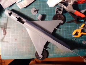
Here’s the work done on the MF so far. Essentially the model builds itself. On this dry-fit picture the only glued parts are the halves of the vertical stabilizer and the rudder, which is offset to port.
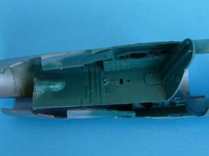
Glued main office parts together and gave them a splash of color – my own mix, which when dried turned out to be very different from the kit-supplied PE variation…
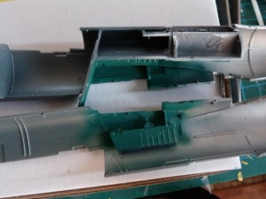
Here you can see the floor. Everything in this area is basically “click-fit”. Rudder pedals were inserted later on.
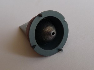
Since closing the fuselage also involves a number of other parts being prepped – I worked on the nosecone. It’s sprayed Revell 62 green, with the aft part in Model Master Burnt Metal and some Revell 93 (copper) to accent the thermal effects on the circular radar housing.
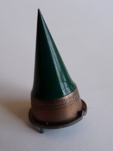
The dots you can see are rows of full-stops printed on decal paper and glued on the “metal surface” 🙂 Because I had no idea about the balance of the model I glued a 15 gram lead fishing weight into the cone, using universal epoxy.
The kit engine is filled with details you will NEVER EVER SEE, unless you have a optical wire-equipped camera. However it lacks the distinctive curved sheet for the afterburner, so I set off to make it by myself:
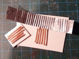
The base for the dies is a 2mm sheet of foamed PVC. I superglued pieces of copper wire. The metal sheet comes from disposable backing dish – really easy to shape, which is helpful if you get some of your attempts lopsided as in the pic here 🙂
Here the entire affair is glued together and painted. Did I mention you aren’t going to see anything if you do not have the right equipment?
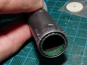
Completing the work on the cockpit, gluing the nosecone, engine and formers in the right-hand half.
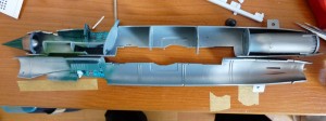
With the basic fuselage construction complete I now turned my attention to the wings. As I intended to drop the airbrakes some drilling and hacking was at hand – the modeller has to open the bays himself and use the supplied parts to comp
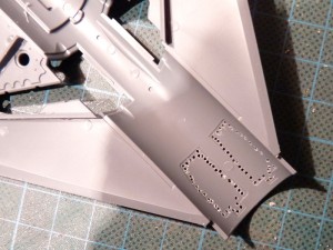
A lot of filing later I ended up with this:
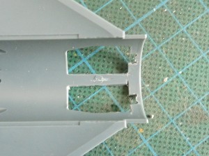
As it turns out I had to use the speedbrakes themselves as a guide – the bay floors are narrower then them…
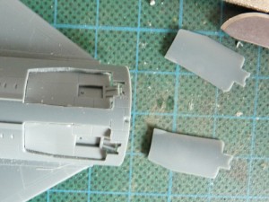
Since I plan a diorama where the aircraft is on the ground and some power supply cables are plugged in it – I drilled out the inlets for the cables:
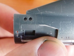
A piece of sprue from Airfix B-26 is placed behind the openings to allow the construction to support the weight of the cables.
Next I worked on the main landing gear bays. The model is cleverly engineered – in order to avoid the limitations of the technology the base of each MLG leg is a separate part. The bays are also boxed in, so you do not see through the entire wing cavity.
Here’s the assembly with some metal paint on:
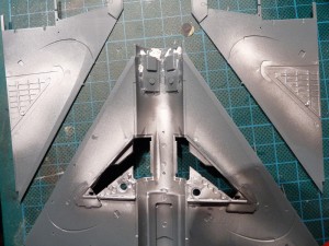
Depending on… SOMETHING the gear bays of the 21s are either green or grey, with the shade varying and weathering with time and use. Here’s my interpretation:
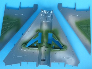
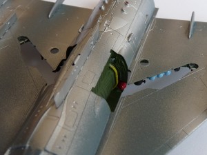
There are a number of oxygen, nitrogen and air high-pressure bottles and of course – the engine compartment sidewalls, doubling as MLG walls as well. Eduard used two more “formers” to shape the unit, which you can see in the middle of the wing here.
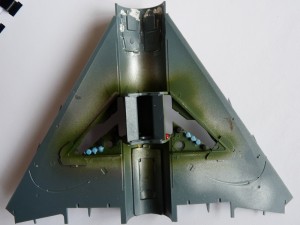
Here’s a shot of the underside. You will notice that I’ve already glued the insert for the dropped ventral speedbrake, as well as the pylons (all of them “dry”).
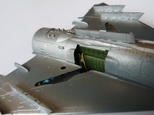
A picture taken from the other side. You can appreciate the detail Eduard has included on this bird. A 490l fuel tank will be hung from the center pylon – the wings of this model are reserved for missiles!
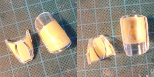
Canopy and windshield masked in preparation for basecoat, cockpit internal color and airframe assembly.
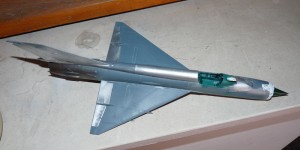
Next – finally it starts to look like and aircraft. On of the few location where filler has been used is between top wings and fuselage, and around the intake ring at the front. Flaps and ailerons are neutral.
The 490l fuel tank is a WELDED affair, made from metal sheets. This means that the WELD must go all around the tank, not just 1/2 of it. I added a weld seam out of stretched Revell sprue (beige), glued with a lot of Humbrol Liquid glue that partially melted it and gave it an uneven look.
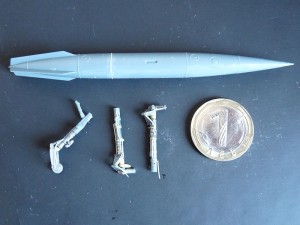
Same material was used to add some hydraulic lines to the gear legs. Part of the details and retaining straps were sources from the Brassin wheel set, others were made from Tamiya tape or aluminum kitchen foil.
Some time, a failed paint attempt, a paint-strip and a number of sanding sessions later the airframe has been sprayed Alclad Polished Aluminum. Note tips of horizontal stabilizers are masked – that’s after they have been painted red.
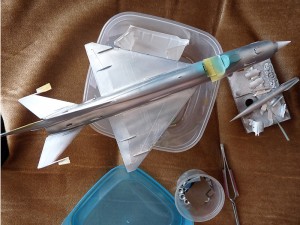
A look to the bottom of the aircraft:
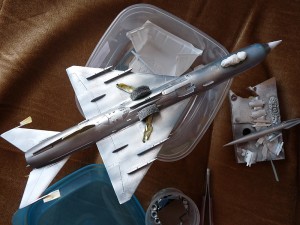
Next: camo, weathering and final assembly.