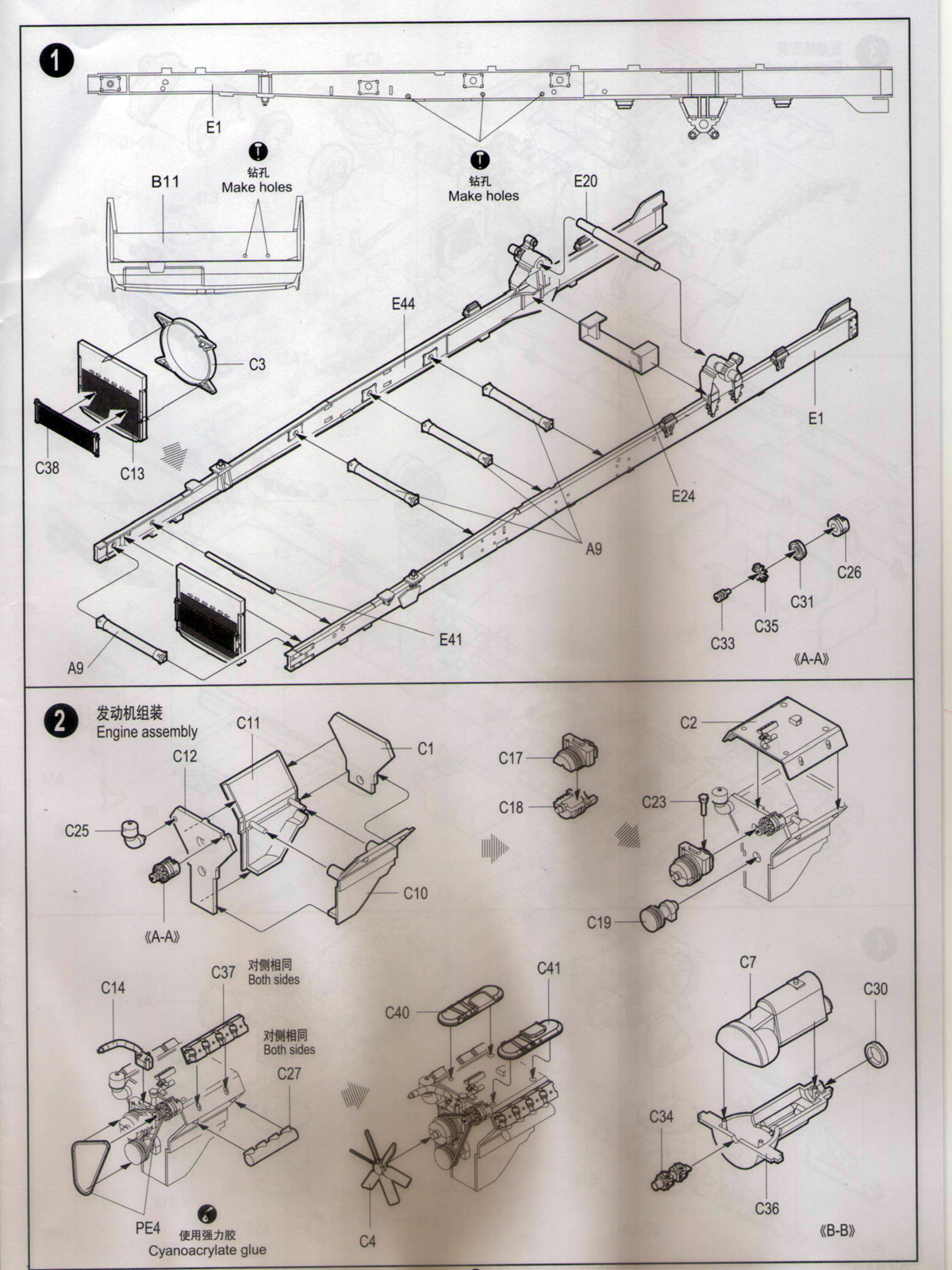
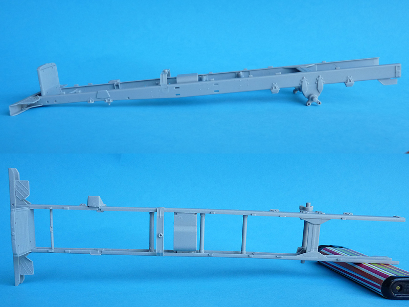
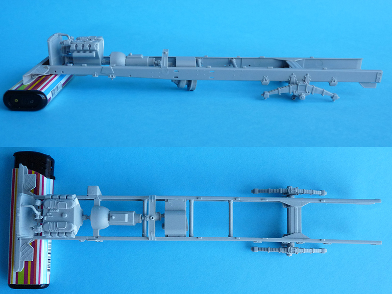
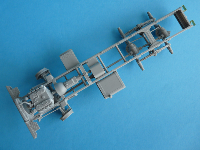
Step 1 – assembling the chassis. You will notice that the radiator group is integrated with one of the spars and is glued here. Almost right behind it is part E41 – the notch in its middle should point to the rear and up. It’s one of the attachment points for the engine block. My advice: align and glue all the spars to one of the girders first, then attach the second one.
The small subassembly in the lower right of step 1’s diagram is the engine alternator, used in the next step.
-
- Trumpeter BM-21 MRL 1/35
-
- Trumpeter BM-21 MRL 1/35
-
- Trumpeter BM-21 MRL 1/35
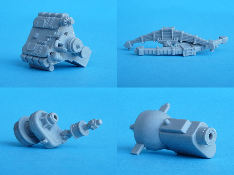
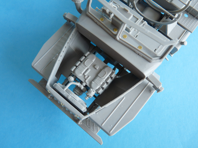
In Step 2 you will assemble the engine and gearbox. They are both very inaccurate in terms of shape and detail, and the fit is less than good. Ridiculously there is a driveshaft between the engine block and the gearbox – the designer is obviously no a driver.
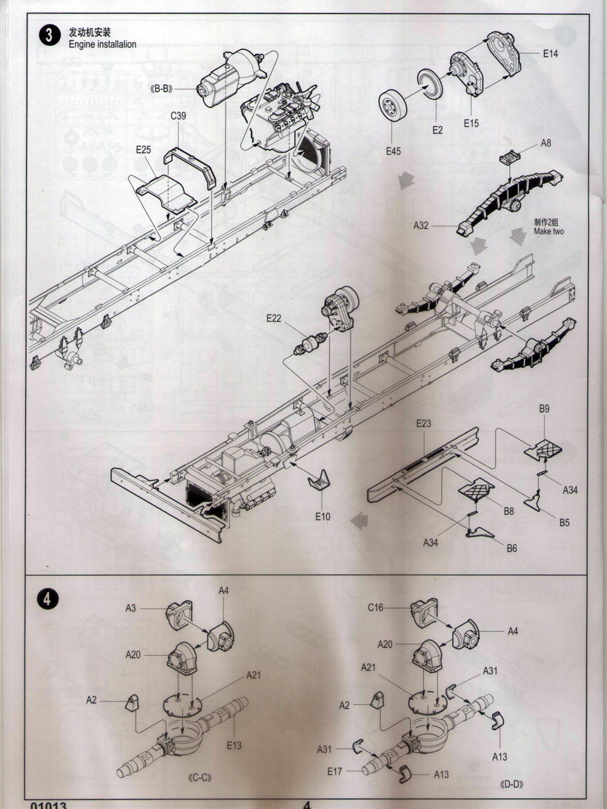
Step 3 – mounting the engine, gearbox, transfer case, front bumper and the rear spring packs. My recommendations:
– I’d add part E25 in step 1,
– test fit the transfer case. Check the fit of its flywheel (parts E2 and E45) against the chassis (I had to trim E2 to have it fit).
– leave the engine, gearbox and transfer case off until step 5.
– simply push the spring packs in place without gluing them and don’t bother with aligning – adding the other suspension parts will do that for you.
-
- Trumpeter 1/35 BM-21
-
- Trumpeter 1/35 BM-21
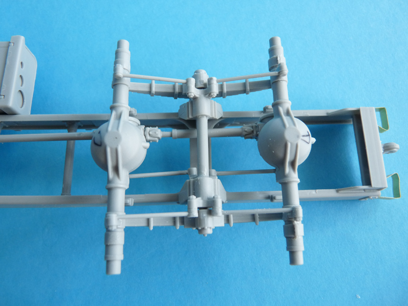
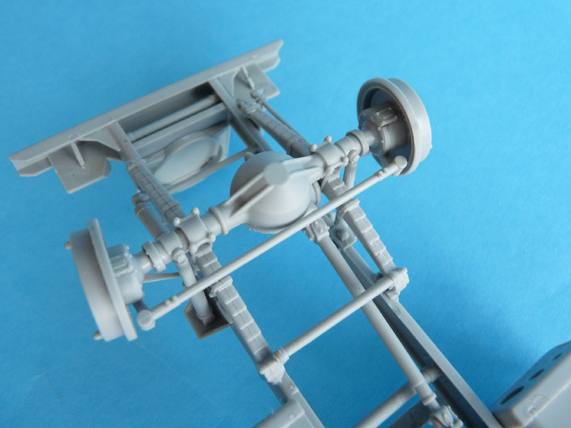
Step 4 – assembling rear axles. These are NOT identical, so label the parts for each accordingly to not mix them up or they won’t fit.
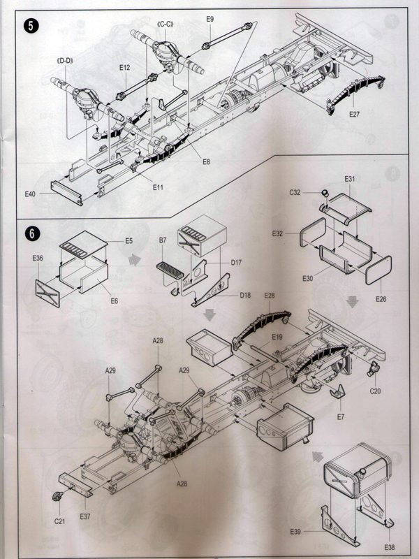
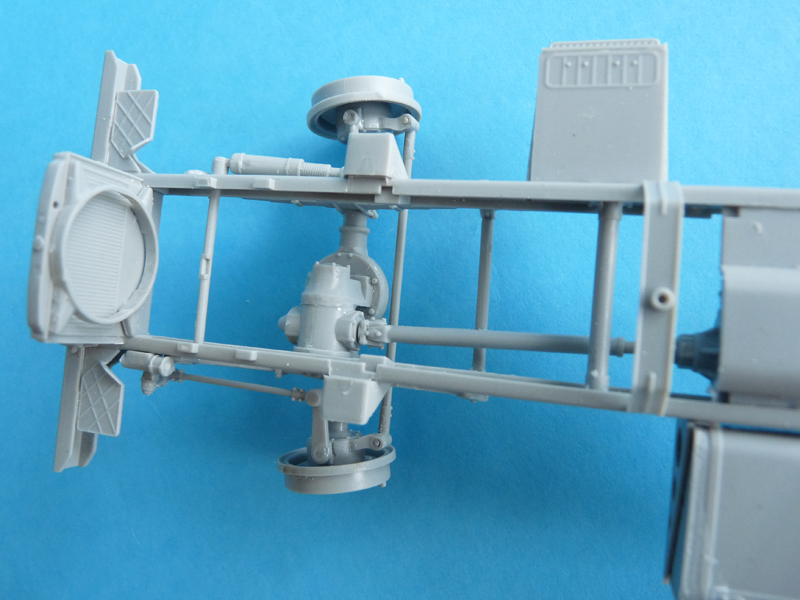
Step 5 – rear bogey and driveshafts. Start by adding the third axle (assembly D-D), then driveshaft E12 and the second axle (assembly C-C). Next add driveshaft E9 to the second axle, then to the transfer case; set the transfer case in place on part E25. Now that you made sure there will be NO bent driveshafts, suspension and chassis, you can add the gearbox and engine, which are NOT structural assemblies and will be hidden from view anyway.
Parts E8 and E11 are placed asymmetrically – only on the right-hand side – and have the corresponding mounting notches.
-
- Trumpeter 1/35 BM-21
-
- Trumpeter 1/35 BM-21
-

- Trumpeter 1/35 BM-21
Step 6 – battery box, fuel tank, front springs. The fuel tank has its retaining straps molded on the halves, so some careful sanding will help avoid losing detail. Check the fit of the tanks with its supports against the chassis – I had to shorten the locating pins for the tank to fit properly.
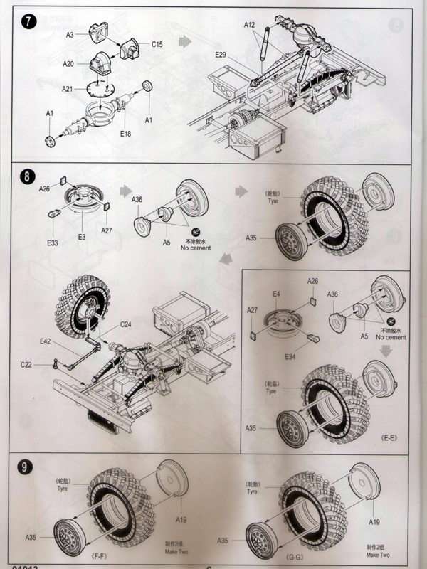
Step 7 – mounting the front axle. To fit the two shock absorbers (part E12) to the U-shaped parts E10 and E7 as shown – please cut a sector off the top of their circular mounting lugs.
Step 8 – front wheel assembly. If you follow the instructions and don’t use glue everywhere the wheels can actually be made steerable. Because they are correctly cinematically connected this will also move the steering rod. Trumpeter beats Dragon by a large margin here by making only 1 mistake in the instructions – they switched the wheel assemblies for left and right.
Wheels and tires (steps 8 and 9). Observe the “direction of rotation” arrow on the tires – the “elochka” (herringbone) thread pattern should always point downwards when looked at from the front. Note that the tire material is resistant to modeling glue.
-
- Trumpeter 1/35 BM-21
-
- Trumpeter 1/35 BM-21
-
- Trumpeter 1/35 BM-21
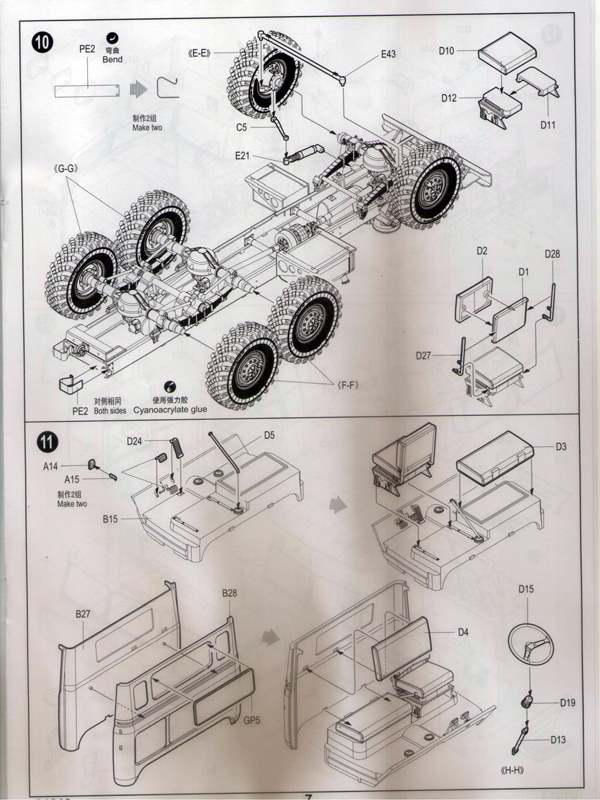
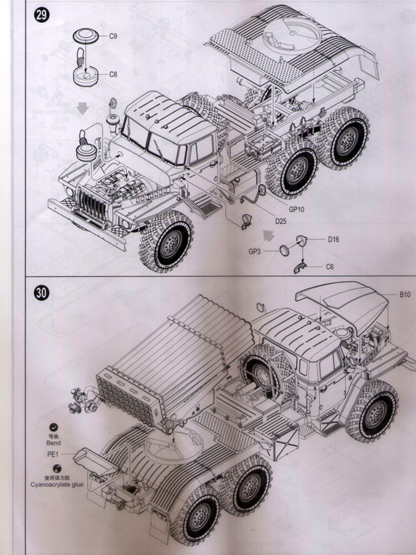
Step 10 – adding wheels, driver’s seat and rear bumper. The two PE details for the rear bumper have NO markings that show you where to bend them. What I did: marked about 0,5mm after the bolt heads, marked the remaining length of the PE strip in 3 equal parts, and bent at the marks.
-
- Trumpeter 1/35 BM-21
-
- Trumpeter 1/35 BM-21
Step 11 – cab floor and rear wall. This step defines the shape of the cab. My advise is to NOT clamp the rear wall to the floor to prevent it from being too inclined forwards. Test-fit the cab ceiling at the top to set the back wall to the correct angle.
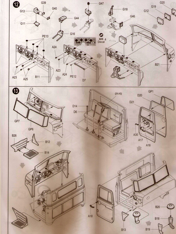
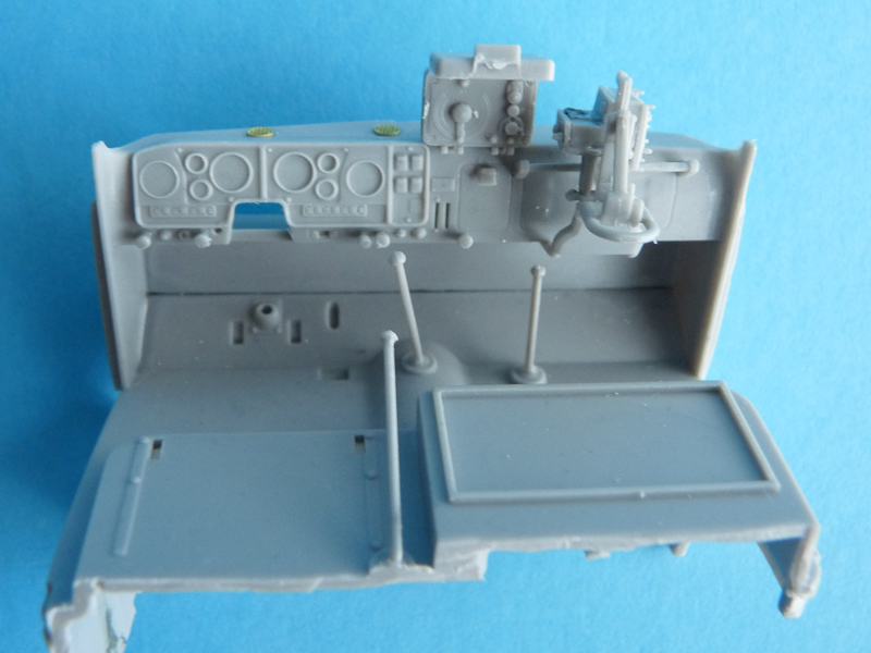
Step 12 – dashboard. Two funny moments here:
– the instrument panel decal goes over the separate switches you just installed per instructions (parts A23, A24), so you can cut off the offending portion of the decal and just paint said switches.
– the launcher control box in the middle of the dashboard can be posed open without its lid (part G12) – there are details molded in the middle part (G19). Depending on the vehicle the box halves (part G12 and G19) can be black or camo color; control panel is black.
-
- Trumpeter 1/35 BM-21
-
- Trumpeter 1/35 BM-21
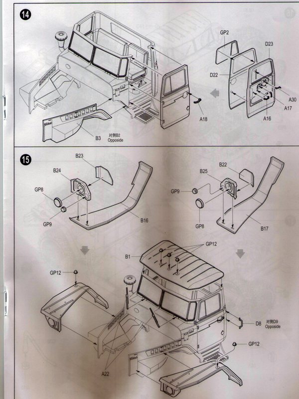
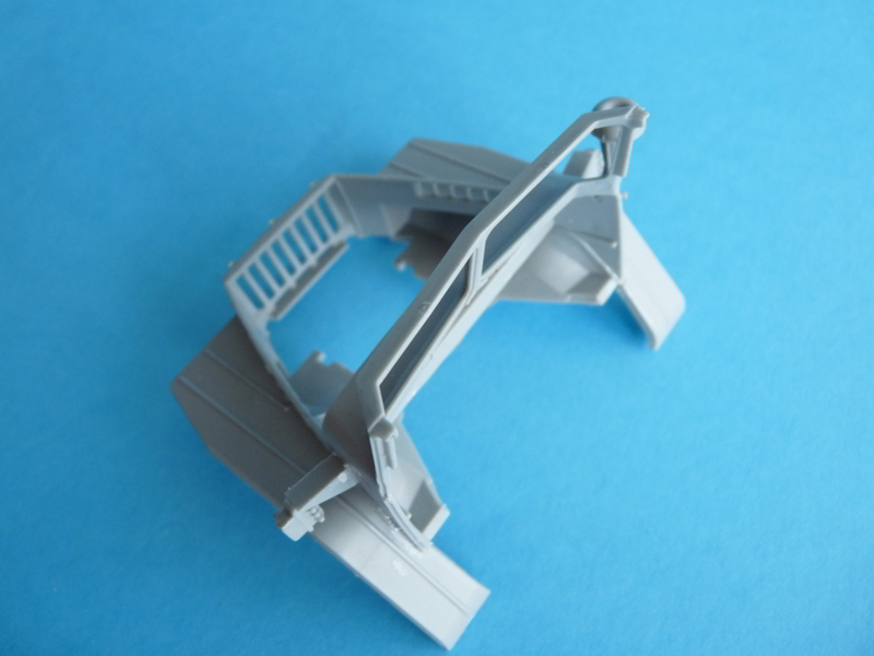
Step 13 – air intake, cab windows, doors and steps. The air intake assembly (parts B18, B19 and B20) should be mounted slightly angled forward. Amongst other things this allows for the right-hand mirror to be positioned properly. The circular detail below the intake is the grounding socket used when the machine will be fired.
Door halves are actually a pretty good fit. If you clamp them too tight they might bend so be gentle. The various handles have either too long or too large mounting pins –test fit before you add them to the doors. I painted mine chrome as they appear on new vehicles.
As the steps on either side of the cab are attached using only a single surface, I would recommend test fitting the steps with the front cab and against the corresponding fenders (no earlier than step 15).
Note all windows have black rubber seals, which Trumpeter has conveniently molded as raised detail – this will greatly simplify masking. Clear parts are flat just like on the real thing, distortion-free, and fit pretty well in their recesses.
Step 14 – adding the doors. Trumpeter actually has the hinges in the right place and raised enough so you can mount your doors open. I did manage to shave the hinges in the kit off, so they were rebuild using round styrene stock.
I glued pieces B2, B3 and B4 together and to the cab front at this time, using thicker glue (Humbrol Poly Cement). As there are NO locating tabs to align them – I used the bare chassis as a jig to put them together properly. Remove the locating stub on part C39 – it is about 1,5mm too far forward and will lift the rear end of the cab if you didn’t.
Even if you glued the engine and transmission you can still maneuver the whole cab assembly around them and set it in place (positive effect of the lack of detail on the engine block).
-
- Trumpeter 1/35 BM-21
-
- Trumpeter 1/35 BM-21
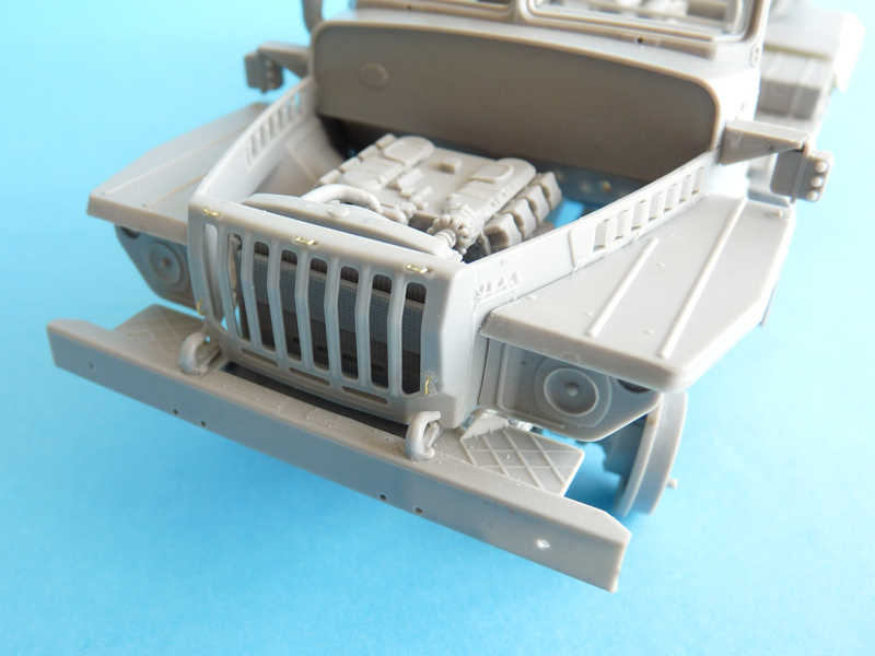
Step 15 – fenders. What I did was gluing parts B16 and B17 directly to the sides of the engine compartment, before adding the B23/24 and B22/25 assemblies. The locating tabs on parts B24 and B25 had to be removed – the corresponding mounting slots on the fenders were about 0,8mm too far back.
A few words about the lights themselves. Depressions for the headlights’ reflectors are too shallow. The parking lights/turn signals above them have a clear (white) lower half and clear orange upper half. Turn signal repeaters on fenders are clear orange. Roof lights (switched on when the vehicle has something on tow) can be transparent or clear orange.
Windshield wipers: their locating pins are way too short. You need at least 2mm extensions to get the wipers to sit flat against the glass panels as on the actual truck.
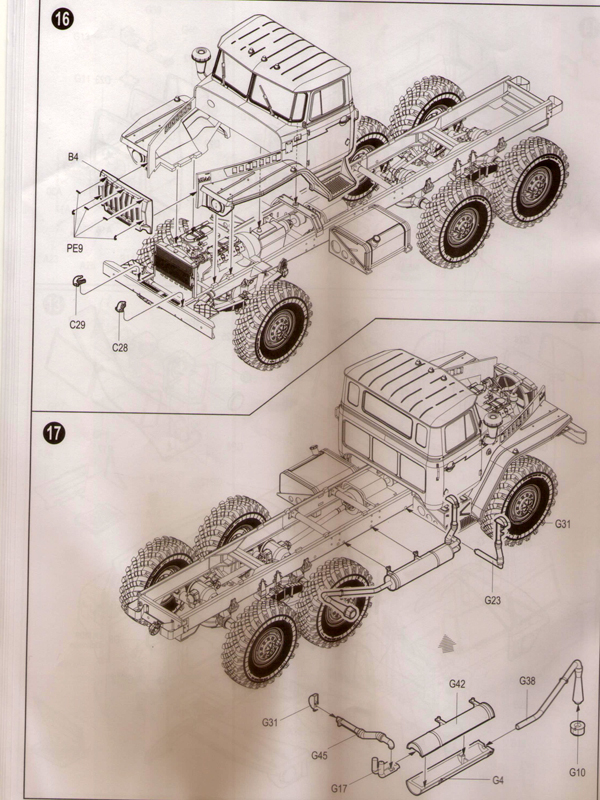
Step 16 – mounting the cab. The kit needs 10 more copies of part PE9 to replace the barely-molded ones on each side of the hood/bonnet.
-
- Trumpeter 1/35 BM-21
-
- Trumpeter 1/35 BM-21
-
- Trumpeter 1/35 BM-21
Step 17 – exhaust. I omitted part G10 altogether. Instead I cut off the locating pin and drilled out the cone on part G38. This provided a much more realistic finish of the part.
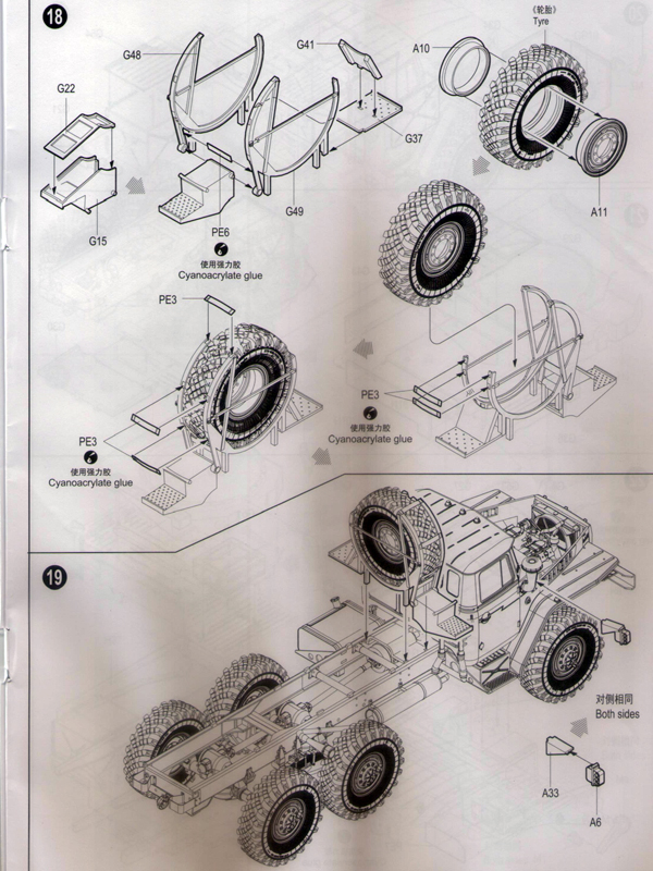
Step 18 – spare wheel assembly. Part PE6 is too short, so you can use the spare part PE3 instead (there are six PE3s on the fret and only 5 are used as per instructions).
-
- Trumpeter 1/35 BM-21
-
- Trumpeter 1/35 BM-21
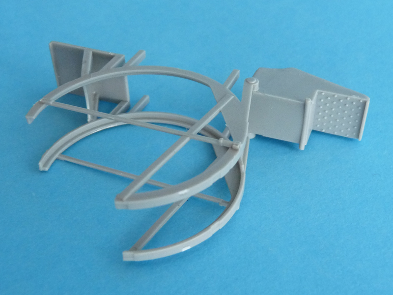
Step 19 – I’d recommend installing the spare wheel frame after the toolkit assembly is attached to the chassis (step 23).
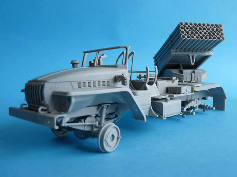
The odd-looking details on both sides of the cab are control light blocks (top to bottom: blue, green and red). These were used to visually indicate the vehicle’s readiness to fire to the battery commander.
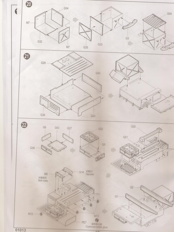
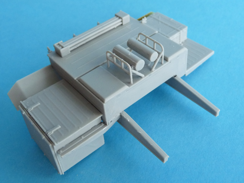
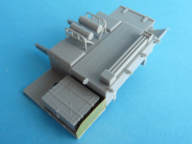
Steps 20, 21 and 22 – toolkit. Pretty straightforward if you follow instructions. The two cylinders at the top of the assembly were actually boxes as well, not pressurized tanks.
-
- Trumpeter 1/35 BM-21
-
- Trumpeter 1/35 BM-21
-
- Trumpeter 1/35 BM-21
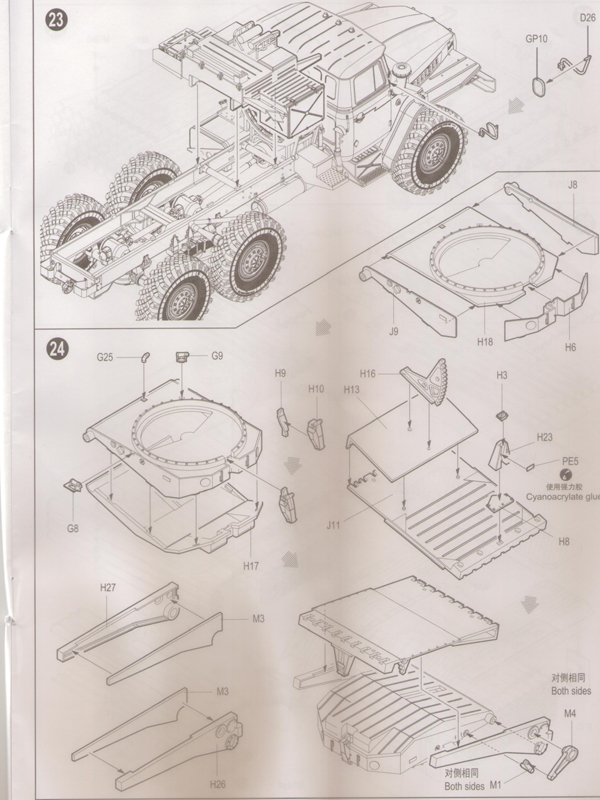
Step 23 – mounting the toolboxes and mirrors. Both mirrors have a black rubber seal around the edge – it can be seen on both the front and back. The non-mirror reverse could be black plastic, painted camo color or left natural metal.
-
- Trumpeter 1/35 BM-21
-
- Trumpeter 1/35 BM-21
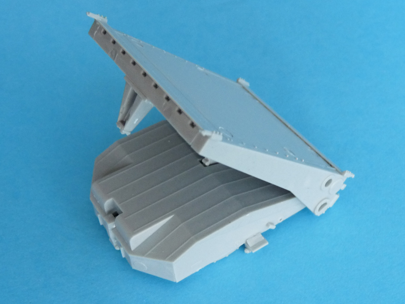
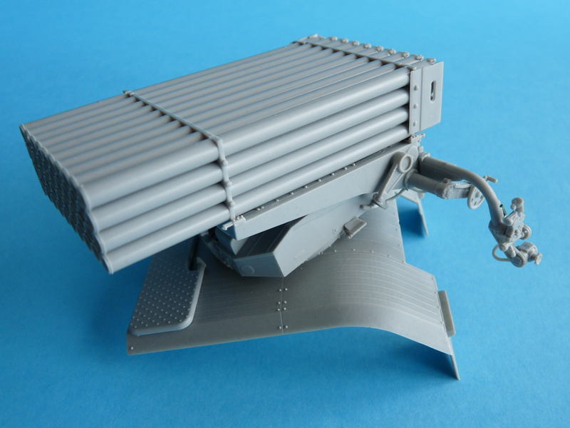
Step 24 – launch pack turntable. If you’d like to set your launcher at a different angle – this is the moment to do it.
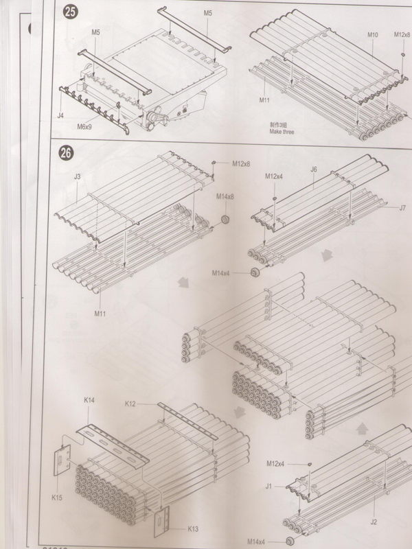
Step 25 and 26 – additional details on the turntable plus building up the rocket pack. What you will undoubtedly notice is that the clever engineering employed by Trumpeter minimizes seam exposure here. On the tube exterior there are subtle hints of the grooves that help the rockets spin and thus be more stable in flight. The joints between the three plates on the missile pack rear (K13, K14 and K15) required a bit if putty on my example.
I left the rear caps (parts M14) off for easier painting. However, when trying to mount them at the last step of construction I discovered they interfered with the electric starting socket (parts M12), so if you want your caps on – follow instructions. The caps themselves are of an early type, these are no longer in production or use, and are replaced with a much thinner, flatter design with 6-spoked raised detail.
-
- Trumpeter 1/35 BM-21
-
- Trumpeter 1/35 BM-21
-

- Trumpeter 1/35 BM-21
-
- Trumpeter 1/35 BM-21
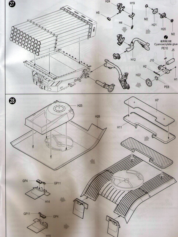
Step 27 – aiming device. Neither separate parts diagram, not the image of the complete assembly gives enough information on actual part placement and color, so pictorial reference is a must.
Step 28 – launcher base, mud flaps and tail lights. The base is a pretty simple affair, and it lacks the bolts that attach it to the chassis. Mud flaps: the wide flat areas on parts H14 and H15 are actually rubber, so you need to paint it the respective color. Tail lights: outer 40% is clear orange, the rest is clear red (there are actually lines on part GP4 you can use as guides). Part GP11 must only be present on the left mudflap – it’s the light illuminating the license plate. It’s either camo color or natural metal. The reverse gear light on the right fender should be square-shaped and at least twice as big.
Step 29 and 30 – attaching subassemblies. The launcher can be glued in the firing position – rotated to the left side of the vehicle. As noted earlier the engine is not quire the real thing, and the characteristic hinges on the inside of the hood are missing, so it is best left closed.
-
- Trumpeter 1/35 BM-21
-
- Trumpeter 1/35 BM-21