Alright – so why do I keep labeling articles using the full kit name and number? Because most companies “milk” their designs and have multiple releases using the same basic kit (or some of it). OKB Grigorov has already released the A1 and A2 versions of the M109, kits No 72004 and 72005, respectively.
Back to our initial SPH variant.
What’s the first thing we usually do? Dry fit major components so we’re able to judge size and get motivated by the upcoming result! I sanded the turret base and the hull recess that is intended to accept it a bit. The model is pretty small, yet rather heavy for its size.
Next – the howitzer assembly was glued together and added to the turret using UHU Tac. The commander’s hatch with M2 mount, the hull lifting eyelets and the gun travel support were superglued.Here’s a shot together with the wheels and spades.

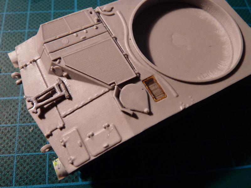
The turret baskets were cut out from the fret, carefully formed and set against the turret rear so I could mark their positions. I drilled small holes to stiffen the whole affair a bit.

You can see the PE turret lifting eyelets and the gas can supports have also been glued.

The rear spades were assembled stowed. I also glued the crescent-shaped pieces that attach them to the hull.

Drilling through parts and adding thin copper wire adds a bit of strength to the assembly and helped align small parts.
I added a support for communications cable reel to the rear door, and a few other details like this tiny PE grill…
Notice the new, bigger headlamp guards that were scratch-built from 0,25mm plastic sheet.
I glued pieces of styrene on the hull nose plates to simulate attachment points for the floatation gear the early machines were equipped with. The rear toolboxes, rear fenders and suspension arms were glued to the hull and turret – see pic below.

The rear lifting hooks are made from different material, since I managed to drop the hull on several occasions and I had to replace the broken items…
The three subassemblies (hull, turret and gun) were now covered with grey automotive primer.

Next step – airbrushing with various shades and mixes of Revell green enamels.


Hopefully the color variation is well evident, though the colors are far from the actual one on the model. I’ve also added an extra part – the shaft for the gun aim cover.
I used the time needed for the enamels to dry to shape the track runs. I used the template drawings on the back of the instruction sheet to create “molds” from 2mm PVC sheet.

The image above can be called BEFORE, and here’s the AFTER:

The track segments respond to hot water rather well. You actually don’t need to use boiling water, perhaps something like 70 degrees would do, with just a couple of seconds needed to soften the track runs.
After they were dry I used the same grey primer as on the other parts, then airbrushed MM Burnt Metal. I brushed Revell 78 to simulate the rubber track pads, then used thinned Revel yellow and sand colors as washes. Lastly they were also dipped in Promodeller’s dark wash – this helps the recessed details pop.
Adding the tracks started with a complete straight section at the bottom of each side. I cut the driving sprockets back in halves, then glued them in the curved track segments – the fit of the teeth between the end connectors is really tight, so apply moderate pressure. Idlers were also glued in their respective sections, and all of this was added to the suspension. All that was left to complete the running gear were the straight sections at the top.
“But Peter, what about the M2 and those gas cans?”
Here you are!

As you remember the M2 barrel was bent, so I chopped it off and used a needle tube to make a replacement.The ammo box and its support were soldered – the parts are rather thin so this helps strengthen them.
These were them primed and painted.
Next – the finished article.