The king of battle (artillery) is not well represented in this blog, and I plan to rectify this starting with the (relatively) recent Msta-S kit from Zvezda in 1/72. The 2S19 self-propelled howitzer was developed during the 1980s to replace the aging 2S3 “Akatsiya” SPG of the same caliber (and much shorter range + lower rate of fire). It uses a modified T-72 hull as well as torsion bars, wheels and track from T-80 to carry a large turret with a 7 meter-long barrel. The resulting product finally brought the level of Soviet SPG up, nearer to the then-current M109 variants in NATO armies. An interesting feature at the back of the turret is an elevator for transporting shells and propellant charges from the ground up into the turret. This means the howitzer can be continuously fed from the ground instead of relying on the limited ammo supply stored onboard alone. Zvezda has already produced an 1/35 kit which proved popular among modellers. Despite knowing the 1/72 kit is expected a year in advance and the official announcement came on June 1, 2019 – picking the actual article up was exciting.
Since I needed decals in order to complete the model I had to raid the kit collection and source some. The victims were an Italeri M113 and a Revell (Matchbox) M40 SPG. I also used the lettering from their sheets to make up a code for a 5-16th Artillery machine (but sans the yellow weight class sign). Mr. Decal Softer helped the markings get grip and conform to the model surfaces.
The decals were sealed, and I used minimal amount of pigments to add to the dusty appearance. Diluted H2Oils (Burnt Umber and Paynes Grey) were used to simulate the leaks. Mixed with some dry pigments they helped create the mud buildup on the front upper sheet.
Alright – so why do I keep labeling articles using the full kit name and number? Because most companies “milk” their designs and have multiple releases using the same basic kit (or some of it). OKB Grigorov has already released the A1 and A2 versions of the M109, kits No 72004 and 72005, respectively.
Back to our initial SPH variant.
What’s the first thing we usually do? Dry fit major components so we’re able to judge size and get motivated by the upcoming result! I sanded the turret base and the hull recess that is intended to accept it a bit. The model is pretty small, yet rather heavy for its size.
Next – the howitzer assembly was glued together and added to the turret using UHU Tac. The commander’s hatch with M2 mount, the hull lifting eyelets and the gun travel support were superglued.Here’s a shot together with the wheels and spades.
Quick hull and turret assembly, wheels and spades
The turret baskets were cut out from the fret, carefully formed and set against the turret rear so I could mark their positions. I drilled small holes to stiffen the whole affair a bit.
Turret with rear baskets
You can see the PE turret lifting eyelets and the gas can supports have also been glued.
Turret front
The rear spades were assembled stowed. I also glued the crescent-shaped pieces that attach them to the hull.
Spades assembled
Drilling through parts and adding thin copper wire adds a bit of strength to the assembly and helped align small parts.
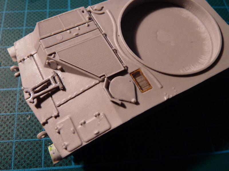
I added a support for communications cable reel to the rear door, and a few other details like this tiny PE grill…
M109 hull front
Notice the new, bigger headlamp guards that were scratch-built from 0,25mm plastic sheet.
I glued pieces of styrene on the hull nose plates to simulate attachment points for the floatation gear the early machines were equipped with. The rear toolboxes, rear fenders and suspension arms were glued to the hull and turret – see pic below.
Next assembly milestone
The rear lifting hooks are made from different material, since I managed to drop the hull on several occasions and I had to replace the broken items…
The three subassemblies (hull, turret and gun) were now covered with grey automotive primer.
M109 all primed up and ready for paint
Next step – airbrushing with various shades and mixes of Revell green enamels.
M109 – roadwheels installedM109 on its feet
Hopefully the color variation is well evident, though the colors are far from the actual one on the model. I’ve also added an extra part – the shaft for the gun aim cover.
I used the time needed for the enamels to dry to shape the track runs. I used the template drawings on the back of the instruction sheet to create “molds” from 2mm PVC sheet.
Track segments and templates
The image above can be called BEFORE, and here’s the AFTER:
Shaped track sections
The track segments respond to hot water rather well. You actually don’t need to use boiling water, perhaps something like 70 degrees would do, with just a couple of seconds needed to soften the track runs.
After they were dry I used the same grey primer as on the other parts, then airbrushed MM Burnt Metal. I brushed Revell 78 to simulate the rubber track pads, then used thinned Revel yellow and sand colors as washes. Lastly they were also dipped in Promodeller’s dark wash – this helps the recessed details pop.
Adding the tracks started with a complete straight section at the bottom of each side. I cut the driving sprockets back in halves, then glued them in the curved track segments – the fit of the teeth between the end connectors is really tight, so apply moderate pressure. Idlers were also glued in their respective sections, and all of this was added to the suspension. All that was left to complete the running gear were the straight sections at the top.
“But Peter, what about the M2 and those gas cans?”
Here you are!
M2, ammo box and support, gas cans
As you remember the M2 barrel was bent, so I chopped it off and used a needle tube to make a replacement.The ammo box and its support were soldered – the parts are rather thin so this helps strengthen them.
Alright, another resin + PE monster from OKB Grigorov, and despite it’s lower Cat. No. (the AT-T was 72007) I got it in the beginning of this year to build for a review.
I must say I liked the kit from first sight. Relatively small number of parts that will make for a detailed, compact model of a vehicle that has a bunch of modifications still in use today, 50 years after its introduction.
So – onto the kit.
All the parts are packaged in zip-lock bags, all protected by bubble wrap and a sturdy white cardboard box. There are
– 85 grey resin parts (with 82 needed for the M109),
– 40 photoetched parts on two frets.
?109 by OKB Grigorov – all the parts together
The instructions (now in color) are obviously snapshots from the 3D software the kit has been designed with. They are printed on an A4 sheet, folded to fit the box. The camouflage and markings are left up to the modeller’s preference, references and decal spares.
M109 by OKB Grigorov – instructions
The quality of resin parts moulding is excellent. Transparent flash can be encountered around some edges and in some openings. That is dealt with in a few swipes of a fine sanding stick or a sharp blade.
I was most impressed with the straight edges of the boxy hull – that level of quality is quite rare even with injection-molded kits. The hull and the turret are two rather heavy resin pieces – no interior, openings, or other resin-saving measures here. Most of the detail – including tools, meshes, grills, bolts, etc. – is cast on the larger resin pieces, the number of tiny parts here is reduced to a minimum.
M109 by OKB Grigorov – hullm109 by OKB Grigorov – hull bottom
There are a total of 58 resin parts comprising the running gear – the track (8 straight sections of T136 track), the suspension arms, driving sprockets, idlers and roadwheels. That’s pretty much half the kit parts. The suspension arms have triangular locating pins which go in corresponding receptacles in the hull. The designers have thoughtfully included a template for the running gear at the back of the instruction sheet – this would help modellers to prepare the track segments for installation over the wheels.
M109 by OKB Grigorov – running gear
There are three optional positions shown for the supporting outriggers at the back of the hull. Two large tool boxes are fixed over them.
The main turret components are the turret casting itself, the M2 mount and the gun assembly.
Turret frontTurret
The latter is made up of three parts: the howitzer mount with recoil cylinders, the gun barrel with its signature fume extractor, and the large cylindrical muzzle brake.
Gun assembly, commander’s hatch, outriggers, gun supports, M2 mount
The M2 with its ammo box, the turret baskets and the 4 boxes attached to them and a pair of fuel cans complete the picture here.
M2, toolboxes, jerry cans, lifting attachments, etc.
The PE parts are on two separate frets of different thickness. The one holding the turret baskets, lifting eyelets and .50 cal ammo is made from 0,3mm copper. The second fret is from a 0,1mm brass sheet.
M109 by OKB Grigorov – PE parts. Left fret is 0,3 mm copper, the one on the right – 0,1mm brass
Below is my rendition of Revell’s 1/72 Hummel, shown in an early camouflage I once saw in a Russian (back then Soviet) magazine. The vehicle profile featured an interesting scheme of Panzergrau with wide hand painted (or sprayed) green “spaghetti”. When a model of the SPG showed up in a local store I decided to recreate the camo as close as my abilities allowed.
Since the build was going to be a kind of sentimental journey I decided to do the Hummel justice and use the opportunities I believed the kit offered – give it a little extra “character” than the box and instructions suggested it might have. I studied the kit reviews and a few build articles, so no surprises were expected. Out were my cutting tools and so – the build began.
I started off with constructing the lower hull and adding the details in the fighting compartment. The ammo storage on the right board was closed with a piece of beer can, the two boxes at the back left open. While the glue on the hull was setting I worked on the plethora of wheels that the Pz. IV-based vehicles feature. Leaving them to the side (without gluing them to the suspension arms though) I got on with the gun.
The details were crisply moulded (no flash) and this made assembling the lafette extra easy. I left the cylinders for vertical adjustment off for the time being as I felt the gun deserved a better faith than being locked on to the travel support. The gun tube was glued in place to the upper lafette, which allowed for vertical movement (as even Revell suggest you don’t glue upper and lower lafettes together). The cylinders for vertical adjustment (the two parts numbered 70) were cut and extended by about 2mm each, using plugs of stretched sprue. When doing this be careful to observe the position of the locating U-shapes at each end of the cylinders as they set the correct position for the gun.
You can’t really see the extensions in the images below as they are now hidden behind that round shield, but anyway – I know they are still in place. After drilling the bore with a 2mm bit I put the gun assembly to the side and scribed off the doors from the back wall of the fighting compartment using the moulded lines as a guide. I was willing to thin the area behind the cooling grills on the side walls enough to be able to see through the holes that’d appear, but while carving away the plastic from the inside a few mistakes proved that idea was too dangerous – the grills would rather break than surrender. If you’re in to work on that area you’ll be better off by either replacing the molded-on grills with etched assembly (as in DML’s kit) or a grill made of scrap plastic.
References how that the correct place for one MP-40 SMG is on the molded-on support of the left sidewall, facing aft. Instead Revell suggests you placed two MP-40s on the back wall, flanking the doors, and glued holders for two M-98 rifles where the SMG should be. You’ll notice that if you decided to leave the ammo boxes below the doors open you’d have to glue the SMGs in a way that’d leave their barrels standing proud over the edge of the back wall. I think that setup’s wrong. Anyway – I had promptly glued the M-98 stock supports and retaining straps according to the instruction and decided to improvize. I placed the MP-40s on the right sidewall, in front of the ammo storage. The three boxes on the left wall were glued without problems.
Next thing – gluing the walls of the fighting compartment to the hull. I started off with the side walls, then quickly added the back one to set the correct angles. Leaving the two front pieces that surround the gun till the end made for rather tricky fit – make sure you dry-fit these before you place any glue on them. Enter the fenders, with jack and light quickly following.
After measuring I discarded the exhaust pipes and produced new ones from solder wire, leaving some extra length and marking the positions for the locating pins. I inserted one end of the solder pieces in the enlarged holes where the exhaust should be coming out from the hull, glued with CA, then bent the solder to follow the sides of the hull – looked like tubes to me! A loop of fine wire where the second locating pin was on the original details secured my “exhausts” to the Hummel’s body. I drilled the “pipes” using 0,6 mm bit in my improvised pin vise.
Paint! Pure Revell 79, a Humbrol brush and thinner from the local hardware store in action. Wheels still separate, as a very large number of them still needed extra treatment for the rubber – old faithful Revell 78 to the rescue! The green lines were made using a Humbrol acrylic formula, part of some airplane set bought years ago. It required at least two passes to cover good enough, so the loops on the superstructure were kind of lost after this intervention.
Once paint is dry along comes the “mud”, represented by a brand of Italian woodworking putty which continues to elude me. The cool thing about is that it is very fine, can be dissolved by water, easily distributed and removed when needed. I use a stiff brush, dipping it into the diluted putty, then pressing it vertically against the hull sides.
Wheels are glued in after this ritual, because otherwise you wouldn’t be able to dirty-up the hull properly. After they are aligned and dier up completely I installed the “link and lenght” tracks. I use light metal color on the latter while they are still on their sprues, then some rust, a thin black wash, followed by a swipe with paper towel and light sanding so the metal below them pops up. When the whole affair is dry enough I detach them, touch up where the sprue gates used to be ane glue them with modelling glue over the running gear. I am still far from doing them straight enough as can be witnessed on those last two shots.
Now some “mud” over the tracks. After it dried I drilled the antena base and made the stick antenna out of a piece of stretched sprue – a bit on the thickish side, really. Final touches – the travel lock, spare roadwheels, a scratchbuild rope with loops and those red-white-and-metal-colored rods below the back entrance. Later on two scratch-made covers were added, made from two-ply paper towels, “impregnated” with dissolved woodworking putty and then rolled, pressed, shaped and painted. Be aware that when drying they change shape.
I lightly sanded some edges to let the metallic base show through, in an attempt to display wear. The whole composition was then covered with dry Agama pigments (I actually did that twice) and sprayed the whole Hummel Revell 02 mat lacquer. Regrettably the mat finish basically flatted the green so much it’s hardly noticeable on the sides, and I’ll be re-visiting the camo sometime soon.