Admittedly I couldn’t wait to start building the kit, so here’s a bit of progress.
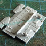
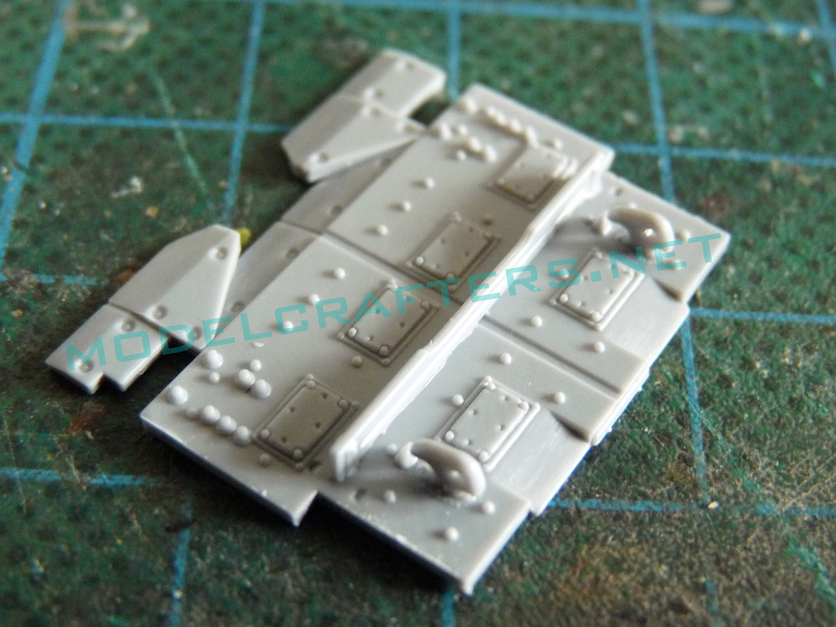
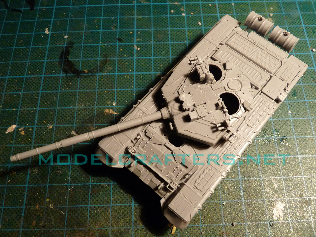
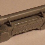
Detailed add-on armor for the upper glacis with wave deflector and towing hooks added.
-
- Building Zvezda 1/72 T-90, part 1
-
- Building Zvezda 1/72 T-90, part 1
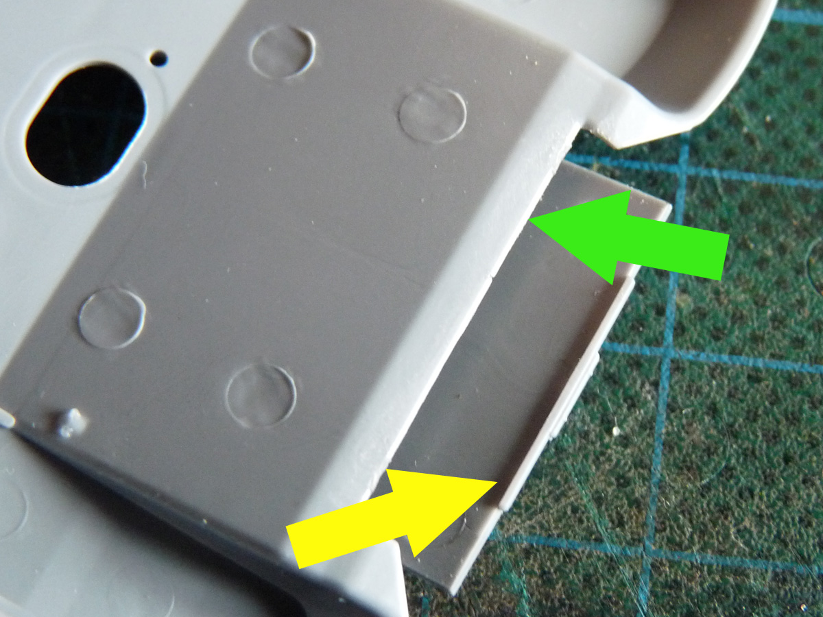
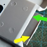
On the second image notice the edge that aligns the add-on armor with the upper glacis (parts reversed to showedges).
Exhaust (3 part assembly) glued in place. Another 2-part assembly (fuel tank for laying smoke screen) covers the exhaust on top.
-
- Building Zvezda 1/72 T-90, part 1

-
- Building Zvezda 1/72 T-90, part 1
The bulldozer blade added to the lower glacis. The sprue gates are mounted between the actuating arms, so I broke one of them trying to clean the part up…
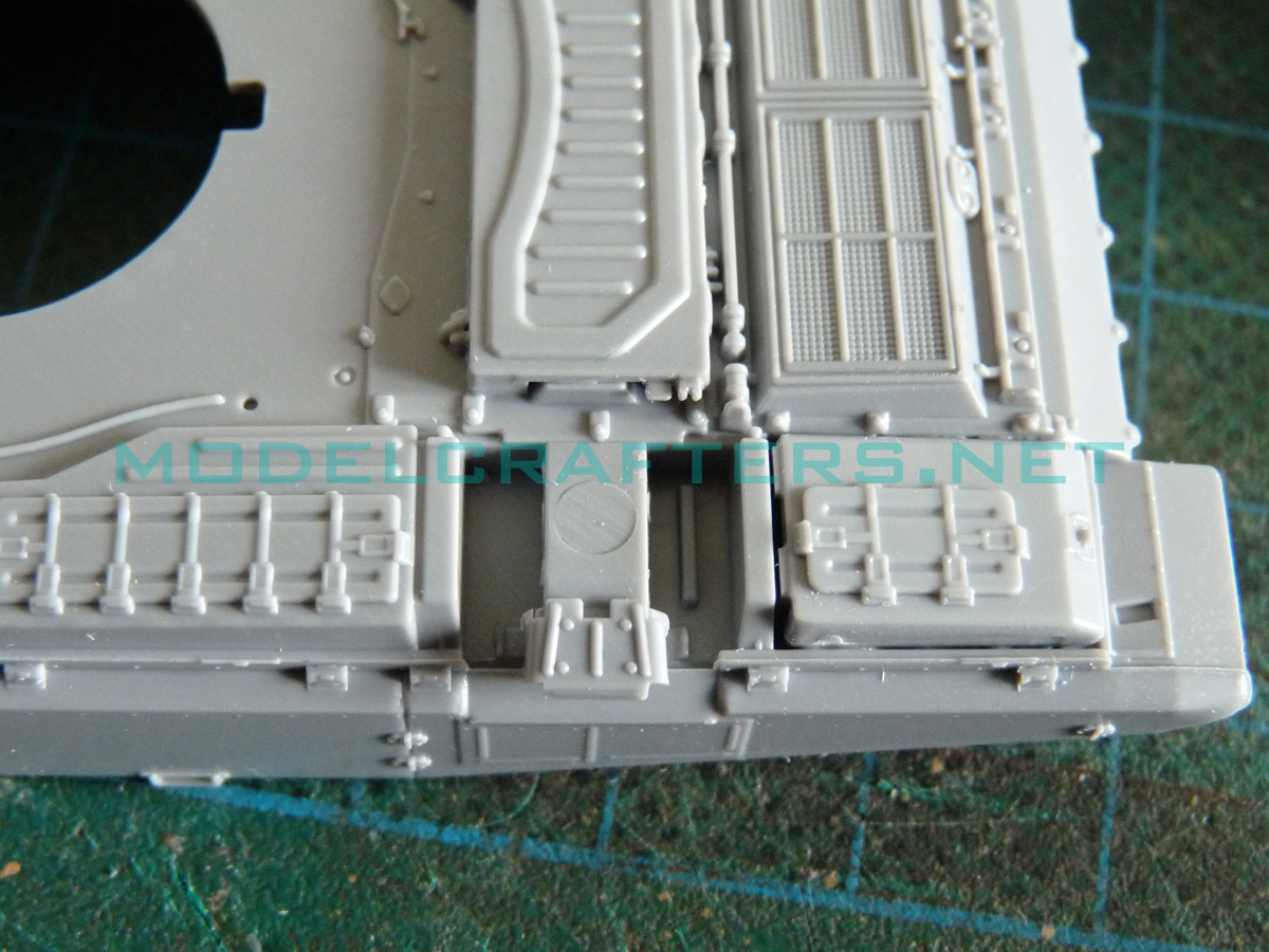
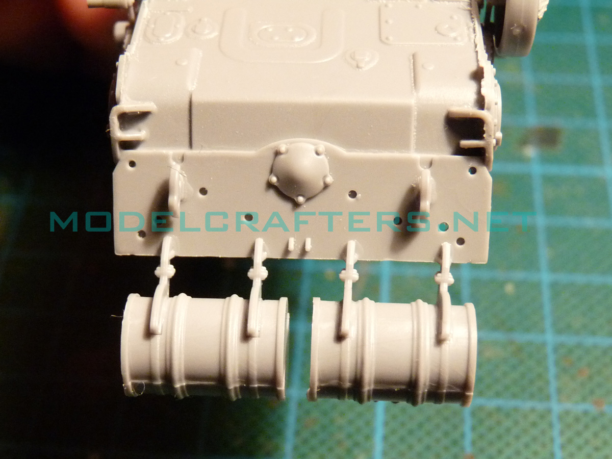
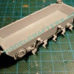
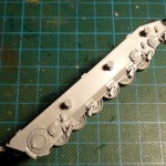
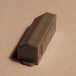
Rear armor plate with fuel drums and supports. I glued the supports, but they only had 1 (one) positive locating pin each, so to align them I added the fuel drums themselves.
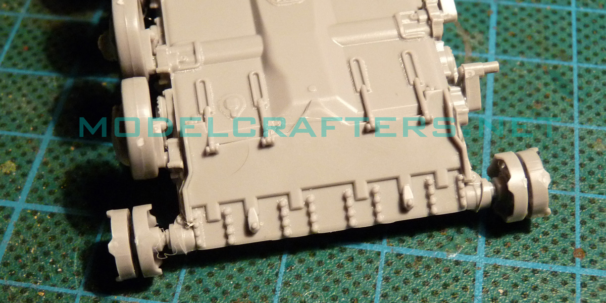
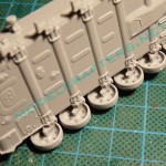
Suspension arms are very easy to install and align on edges molded in the hull pan. You must observe the instruction and mount a different type of suspension unit on station 3: it has a semi-circular pin for a special roadwheel.
-
- Building Zvezda 1/72 T-90, part 1

-
- Building Zvezda 1/72 T-90, part 1
-
- Building Zvezda 1/72 T-90, part 1
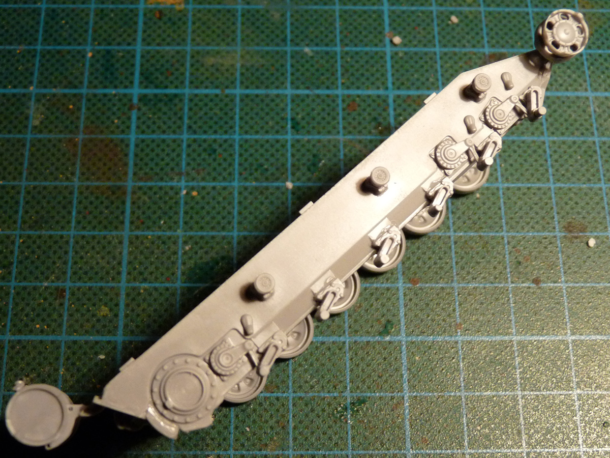
Note: be careful while separating the special suspension arms details for stations 1, 2 and 6 from the sprue. They are particularly fragile, a bit too much tension will easily brake them off.
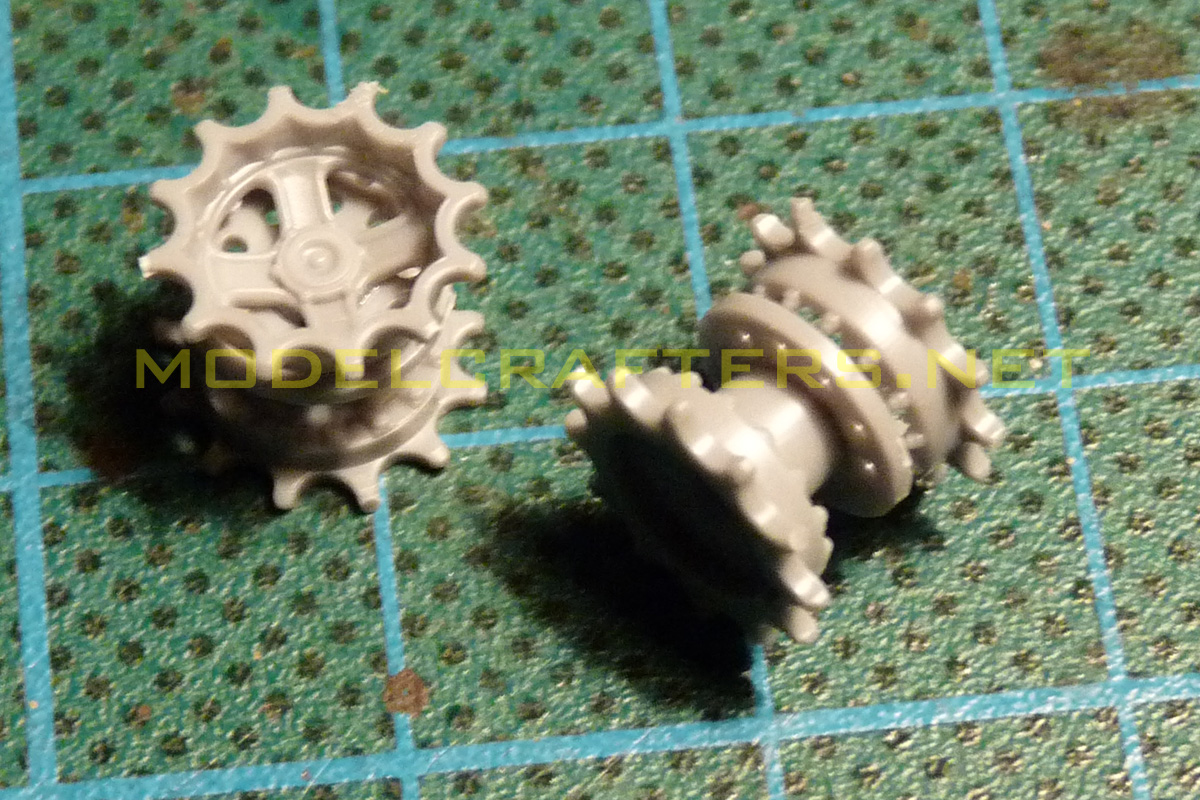
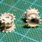
Drive sprockets: 3-part affair, don’t forget the slotted disk in the middle that fits as a collar around the mounting hole.
-
- Building Zvezda 1/72 T-90, part 1
-
- Building Zvezda 1/72 T-90, part 1

Use a long pin or an edge to align the teeth properly.
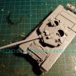
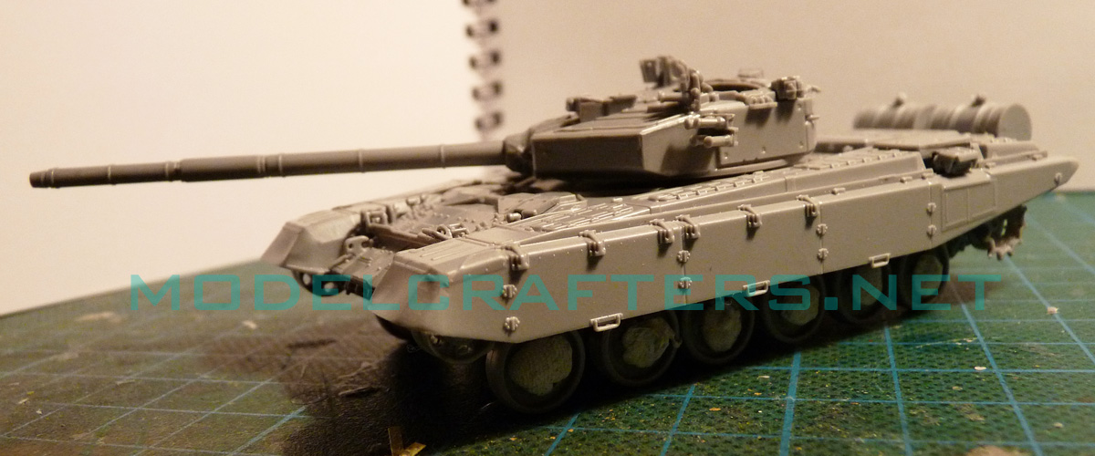
The temporary mockup with upper and lower hull + turret. The wheels are stuck on using UHU tack to see the silhouette and check for adjustments.
-
- Building Zvezda 1/72 T-90, part 1
-
- Building Zvezda 1/72 T-90, part 1
-
- Building Zvezda 1/72 T-90, part 1
-
- Building Zvezda 1/72 T-90, part 1

Note the position lights are mounted on the upper glacis – I did that BEFORE gluing the add-on armor.
Both front light guards (parts C37 and 79) are about 2 mm short on the right-hand side on my example. You will need to extend them using stretched sprue (note this is NOT done on these pics yet).
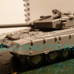
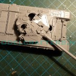
Turret fits just fine, be careful with the position of parts C18 and C19. If reversed the entire assembly will not fit.
Consult reference about the angles of the smoke canister launchers. The tanks on this years Victory parade appear to match the kit’s layout. Same applies for the ERA layout (not added yet).
If you want to rotate the commander’s hatch you will have to shave off the bolt detail on the turret itself.
It is possible to reverse-mount turret side walls and rear armor, please observe the instructions carefully.
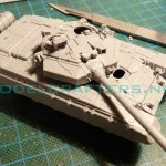
The main gun does feature a mold parting line, sand it away with 800-grit. The line is offset from the thermal sleeve seam, so if you are careful you will not lose detail. The gun tube only gits one way in the receptacle.
Mount the coaxial machine gun at least after gluing the 125mm, otherwise you might end up handling the turret in such a way that you will bend or brake its barrel.
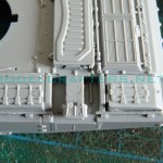
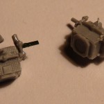
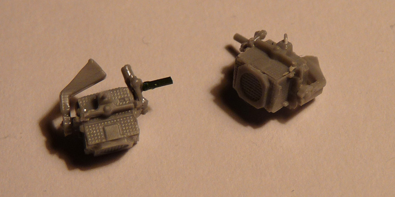
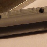
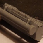
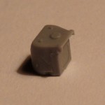
Onto the Shtora cubes. Each of them is 8-part assembly: 6 parts for the sides of the cubes, and 2 mounting supports. Be careful when cleaning parts up for each cube. The simulated support frame transforms into a sprue gate on both sides of each part, so you might end up with gaps like the ones below:
-
- Building Zvezda 1/72 T-90, part 1
-
- Building Zvezda 1/72 T-90, part 1
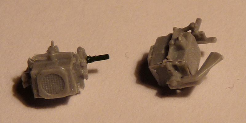
Naturally I broke one of the pantograph linkages and replaces it with stretched sprue. You also noticed my joints are less than stellar – using small amounts of slow-setting glue will be helpful here.
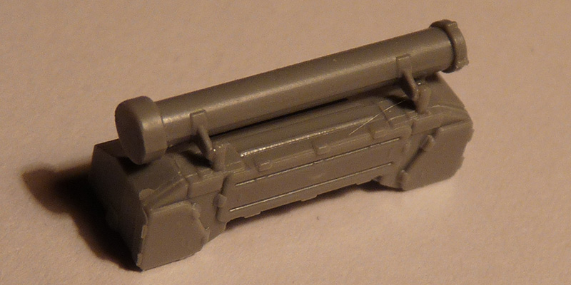
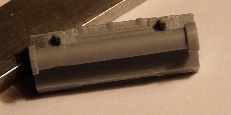
More turret detail storage bins 1, 2 (antenna guard) and 3 (with the snorkel tube):
-
- Building Zvezda 1/72 T-90, part 1

-
- Building Zvezda 1/72 T-90, part 1

-
- Building Zvezda 1/72 T-90, part 1

-
- Building Zvezda 1/72 T-90, part 1
-
- Building Zvezda 1/72 T-90, part 1
-
- Building Zvezda 1/72 T-90, part 1

The tube has small locating pins at the top of the 2 bars it hangs on. If you observe the instruction, they will fit in tiny holes at the end of the pins extending from the bin lid.
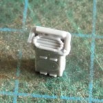
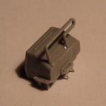
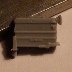
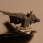
A spare KORD ammo box; note on actual machines the feed opening faces DOWN for obvious reasons. The instruction will have you mount it with the feed up instead.
-
- Building Zvezda 1/72 T-90, part 1
-
- Building Zvezda 1/72 T-90, part 1
The other image shows the gunner’s secondary sight, still not mounted in place.
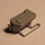
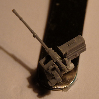
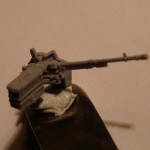
KORD .50 cal machine gun with ammo box and spent casings chute. Looks like a few handles are missing – notably the one for quick barrel change and the firing one.
-

- Building Zvezda 1/72 T-90, part 1
-
- Building Zvezda 1/72 T-90, part 1

-
- Building Zvezda 1/72 T-90, part 1

More to come.