Another Armorama review build. This was one of those rare occasions when I decided to strictly follow the instructions.
I started by test-fitting the turret top and bottom. The locating pins in the turret base detail are too thick, so a step step was formed – they were quickly removed.
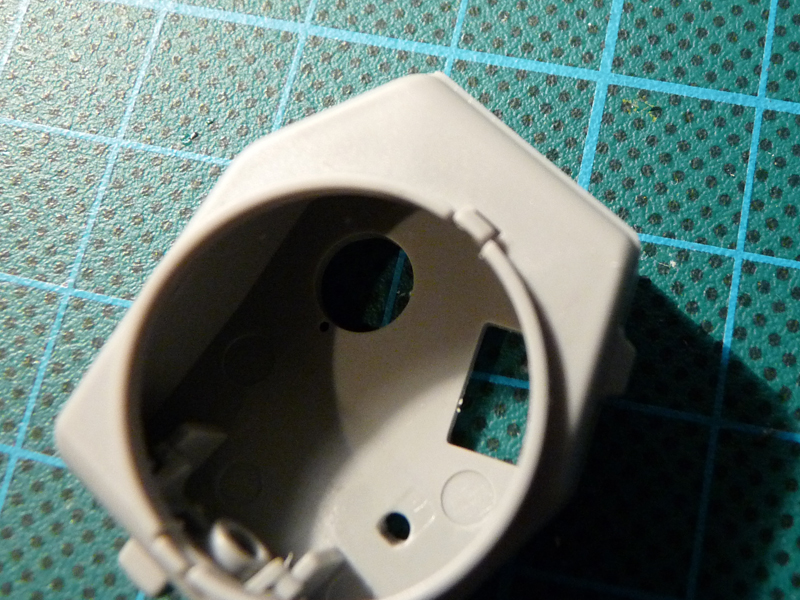
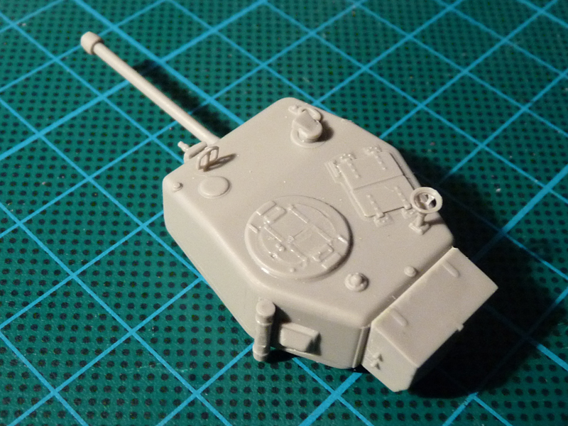
Since two options were presented for the main turret armament (parts C3 and B7) I went with the longer one 🙂 The aft end of the detail required some sanding to fit in the turret mask. Next, the Besa machine gun was glued in the mask. After the assembly was glued to the turret base (C5), I added the top detail (C9) to close the turret.

I proceeded to add the turret bin. There are 4 angular shapes, molded on the rear turret wall – the box has to sit on them rather than fit around them (the bin was mounted some distance away from the turret on the real vehicle). The hatches are separate details, but I decided to model them closed due to lack of suitable crew members. The other turret details are rather straightforward affair.
The tank’s suspension is made up of very few parts and poses no real problems – the fit is rather nice, just make sure the details are parallel to hull sides.
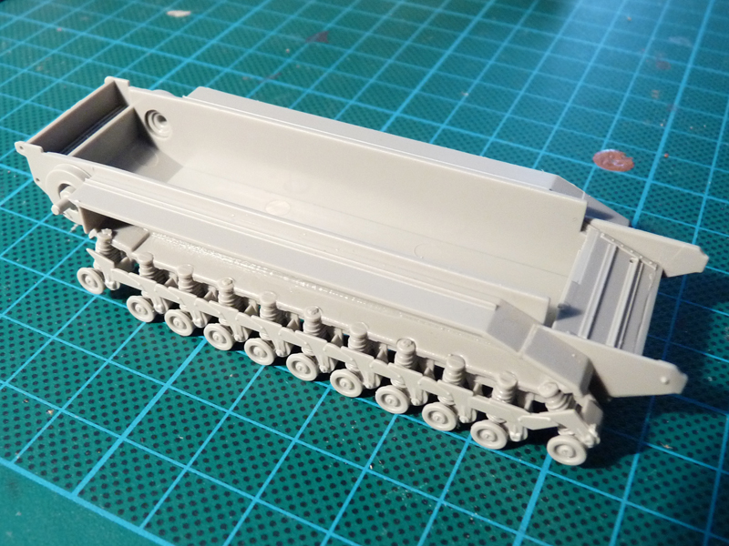
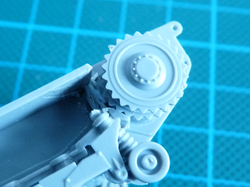
While trying to assemble the driving wheels and the idlers (step 2) I realized the numbers on the part plan and instructions do not correspond to those on the sprue . The diagrams make you glue parts 24 and 25 to form the idlers, but actually that should be parts 24 and 27 as per reference vs. the kit I was reviewing.
You will need parts 25 and 28 to make up the driving wheels. A simple rule to avoid confusion: all details with lightening holes are for the idlers, and the solid details form the driving sprocket.
While test fitting the driving wheel to the hull I discovered the rear end of the sponson box was interfering with the wheel itself. The walls were duly removed, and this will not affect either the appearance or the structural integrity of the finished model.
I thinned the inside of the armor plate in front of the driver. For whatever reason I could not get the detail to fit with the rest of the hull…
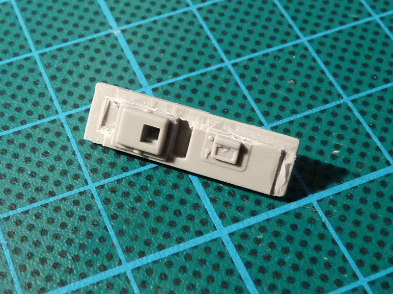
Note this is the inside of the plate and the Besa has not been glued yet. Let’s have the detail added to the rest of the hull.
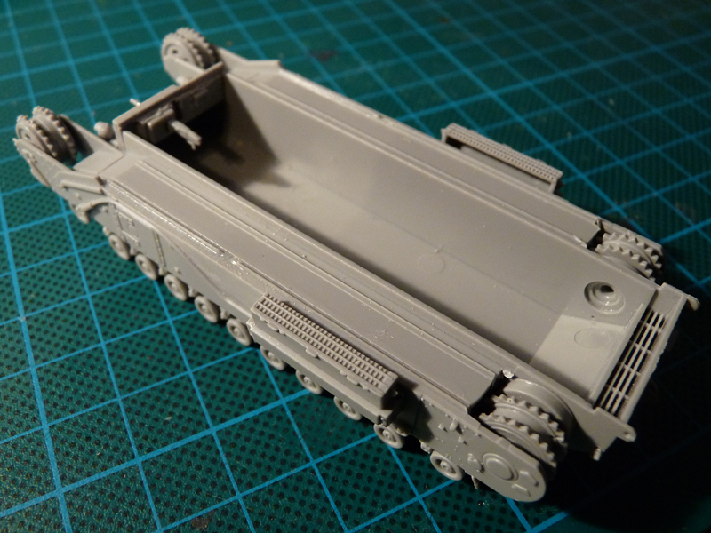
After ensuring the modification has been successful I glued the engine air intakes and painted the hull with a mix of Revell greens.
To avoid overlapping tracks lifting the hull top I shortened the tracks a bit. They were primed, painted Model Master Burnt Metal, and weathered with several browns. The ridges received drybrushed Tamiya X-11 to simulate wear from contact with the terrain.
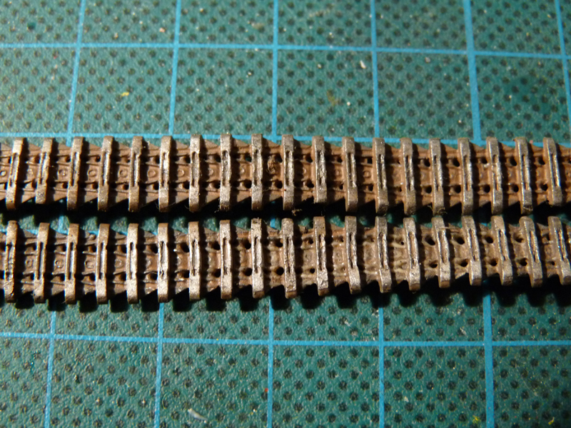
The track runs were then secured to the roadwheels with superglue. Their ends were affixed with copious amounts of Humbrol Liquid Poly to the top of the sponson boxes.
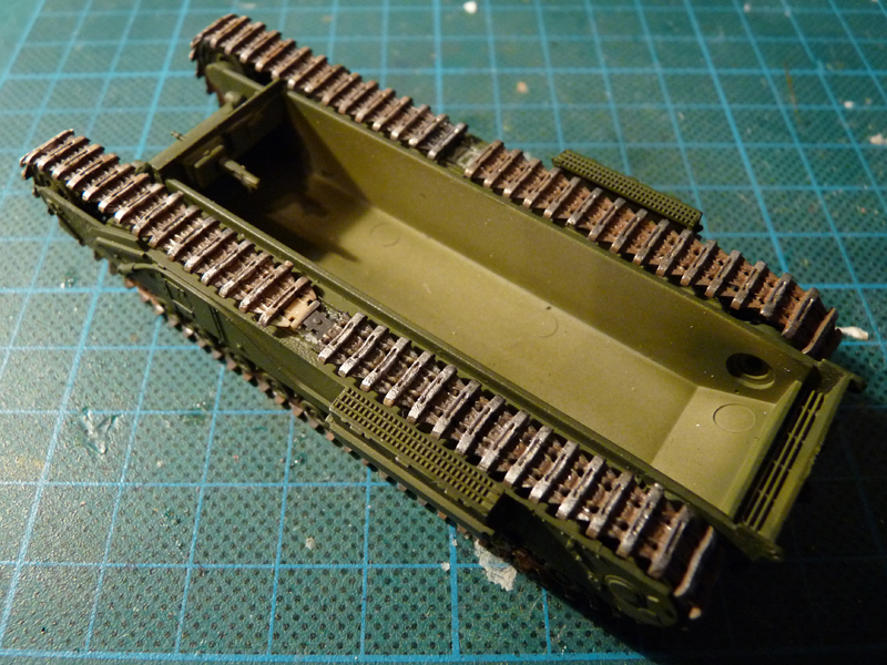
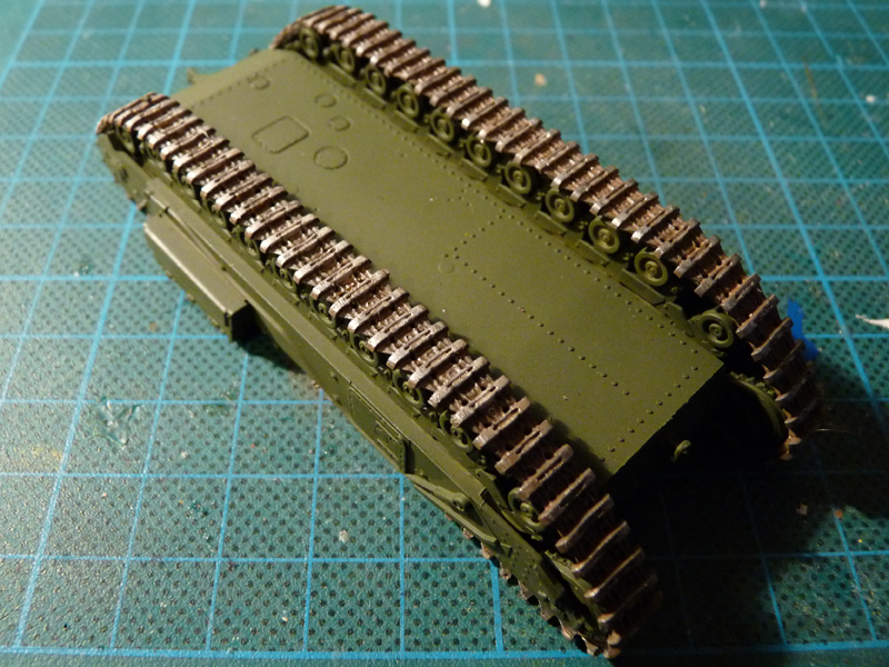
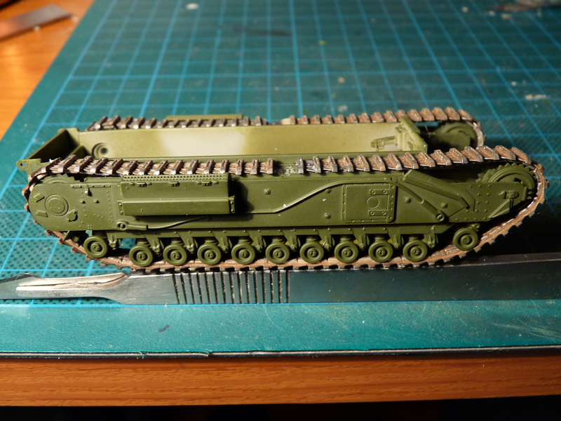
The pre-painted hull top was added after the tracks dried. Exhaust pipes, fuel cans, spare track links and the air inlet covers were glued to complete the assembly. Next step – decals and weathering.