Last night I shared some details of the test shot. Tonight I am posting a few images of the build process.
As you have already noticed this is a complete kit, not a short run one, with a lot of parts and excellent detail. Despite being a test shot the set that I have fits very well. What you see here is bare plastic and glue with the minimal cleanup required so parts fit. No filler or primer was used.
I started with the turret. The locating pins and the shape of the guiding surfaces helped mate the upper and lower part nearly perfectly. I used a bit too much glue, so needed to clean up a bit.
-
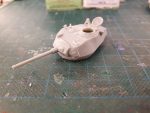
- Turret from front-left

-
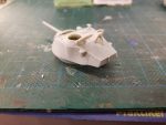
- Turret rear with bin and M2 tripod

-
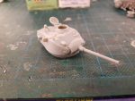
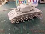
- Right side, note guard and antenna base

The turret bin lies flat against the rear turret wall. The lid is a separate part you can pose open if you so wish. I closed the gunner’s hatch as it’s too large an opening on such a small turret (and I have no figures I can fit in there anyway). The hinges need a bit of thinning to persuade the hatch to fit, some Tamiya Extra Thing would also be helpful.
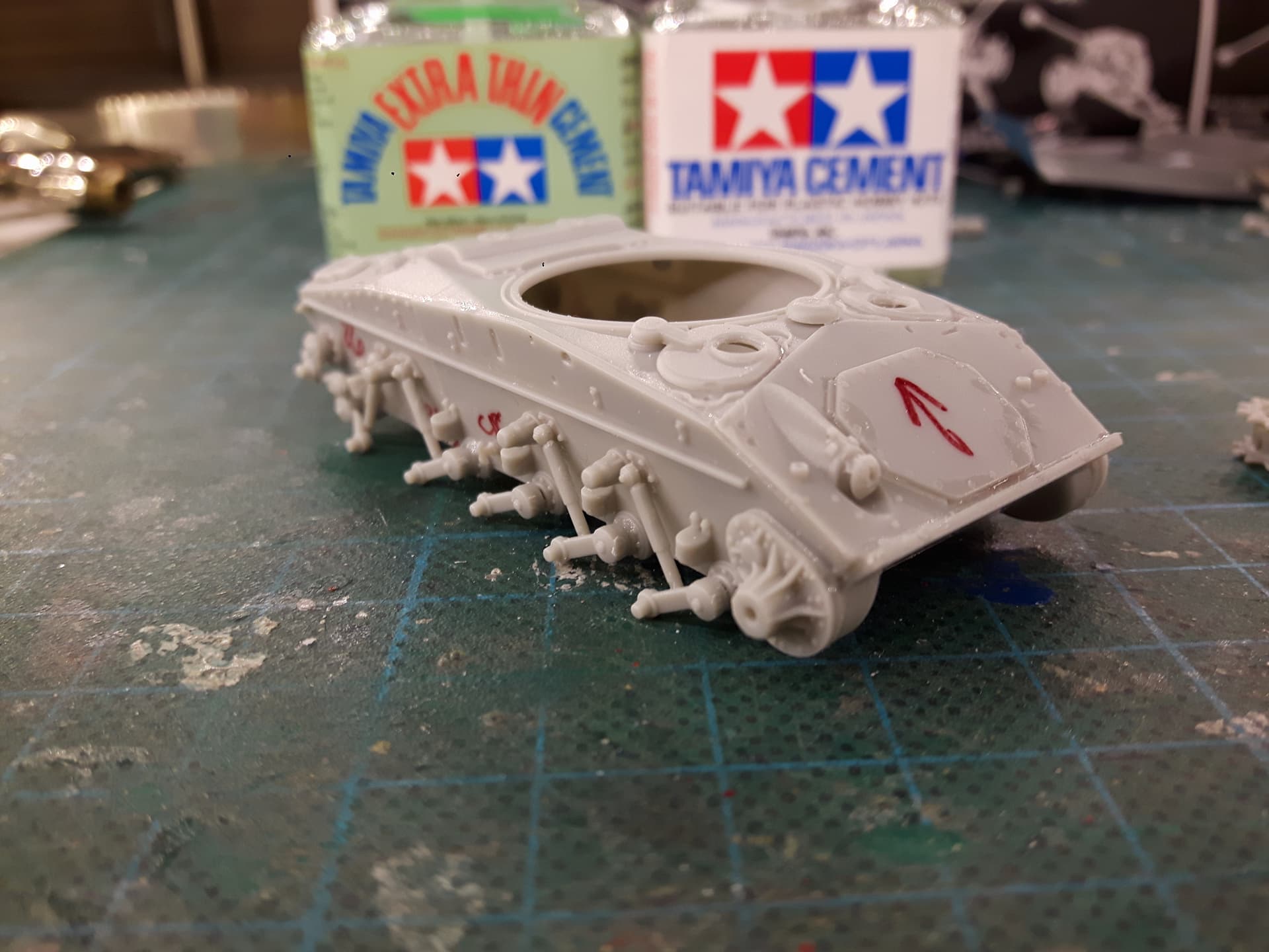
Next I took on the hull. I started by fitting the sidewalls to the bull bottom, and proceeded with the rear wall. I then added the lower glacis. These were all assembled using regular Tamiya cement as it dries a bit longer, which helped align the parts properly, especially once the hull top was added.
-

- Front hull, note machine gun armor fitted
-
- Hatches closed here, too
-

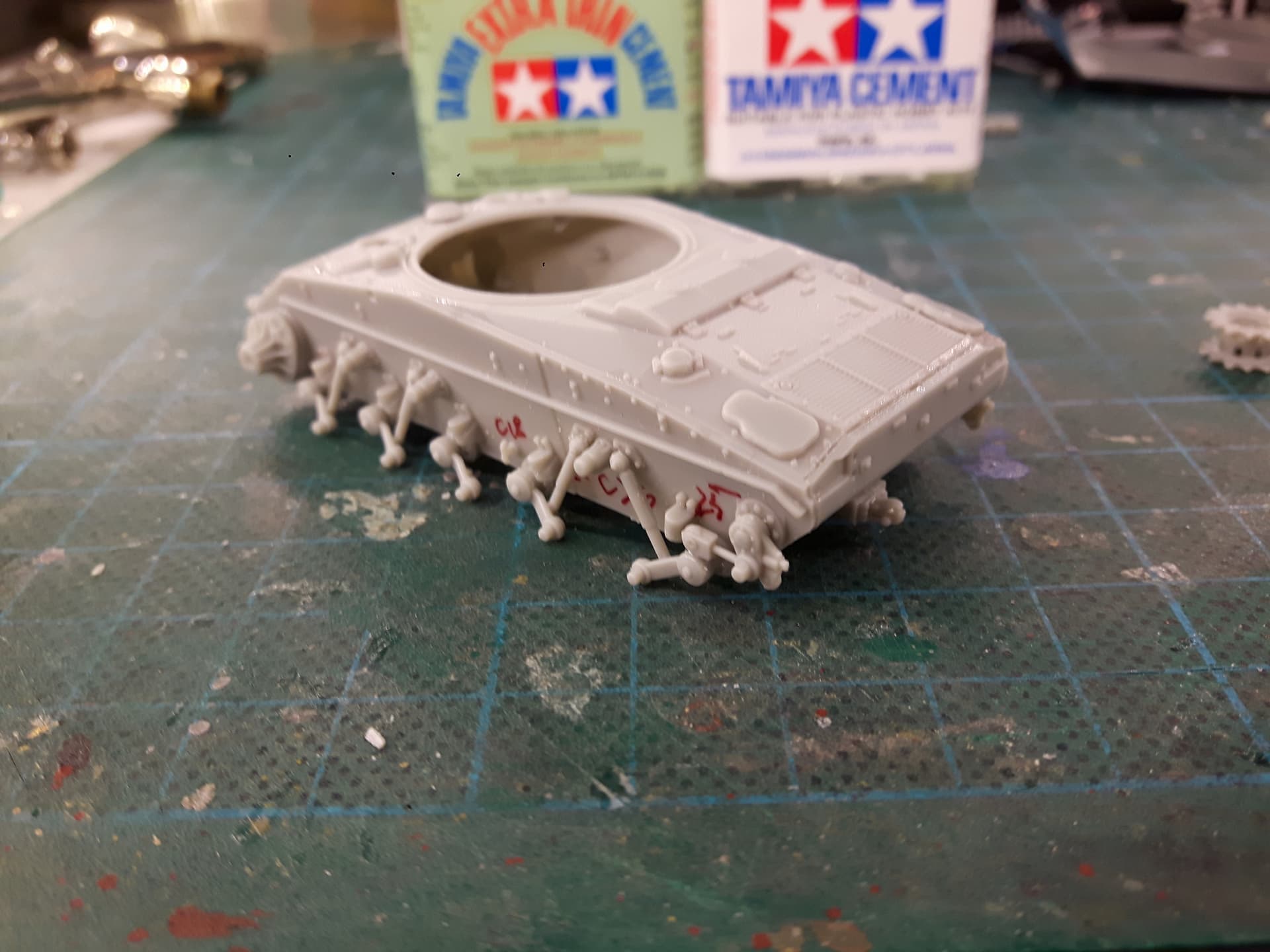
- Suspension and track tensioners
-
- Cooling openings and fuel vents on motor deck

-
- Suspension and hooks on the right

-
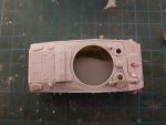
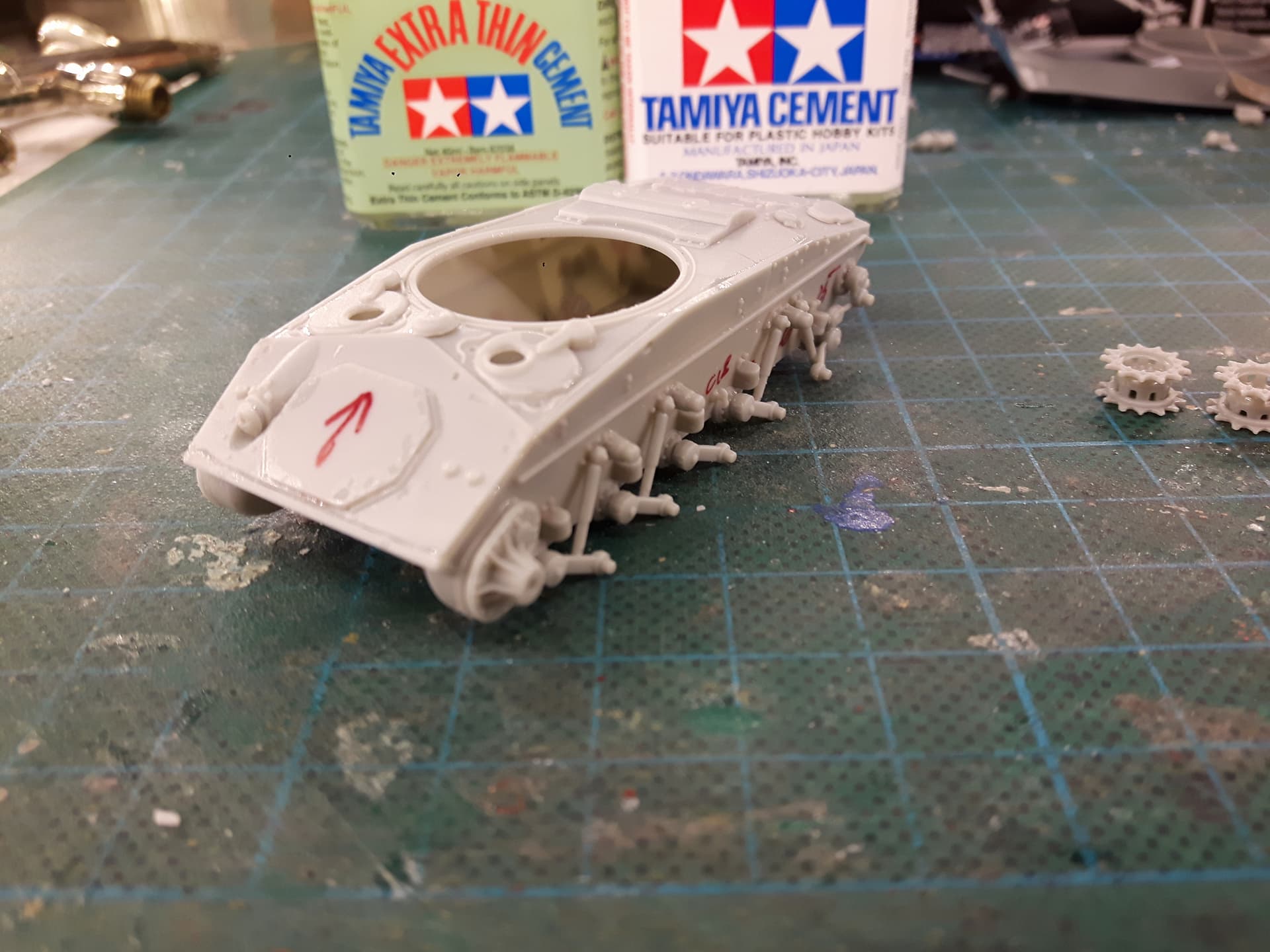
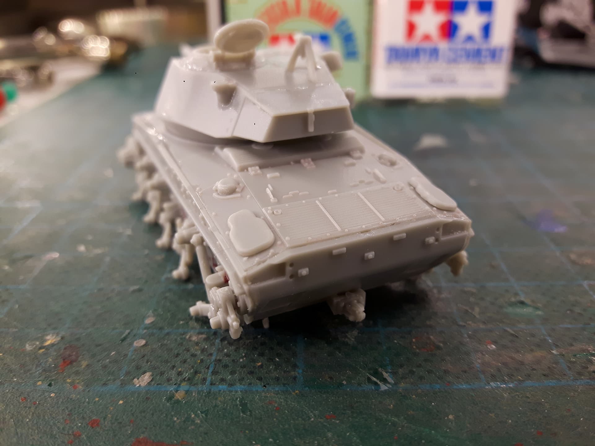
- Note fit of hull top plates vs side walls, upper glacis and rear plate
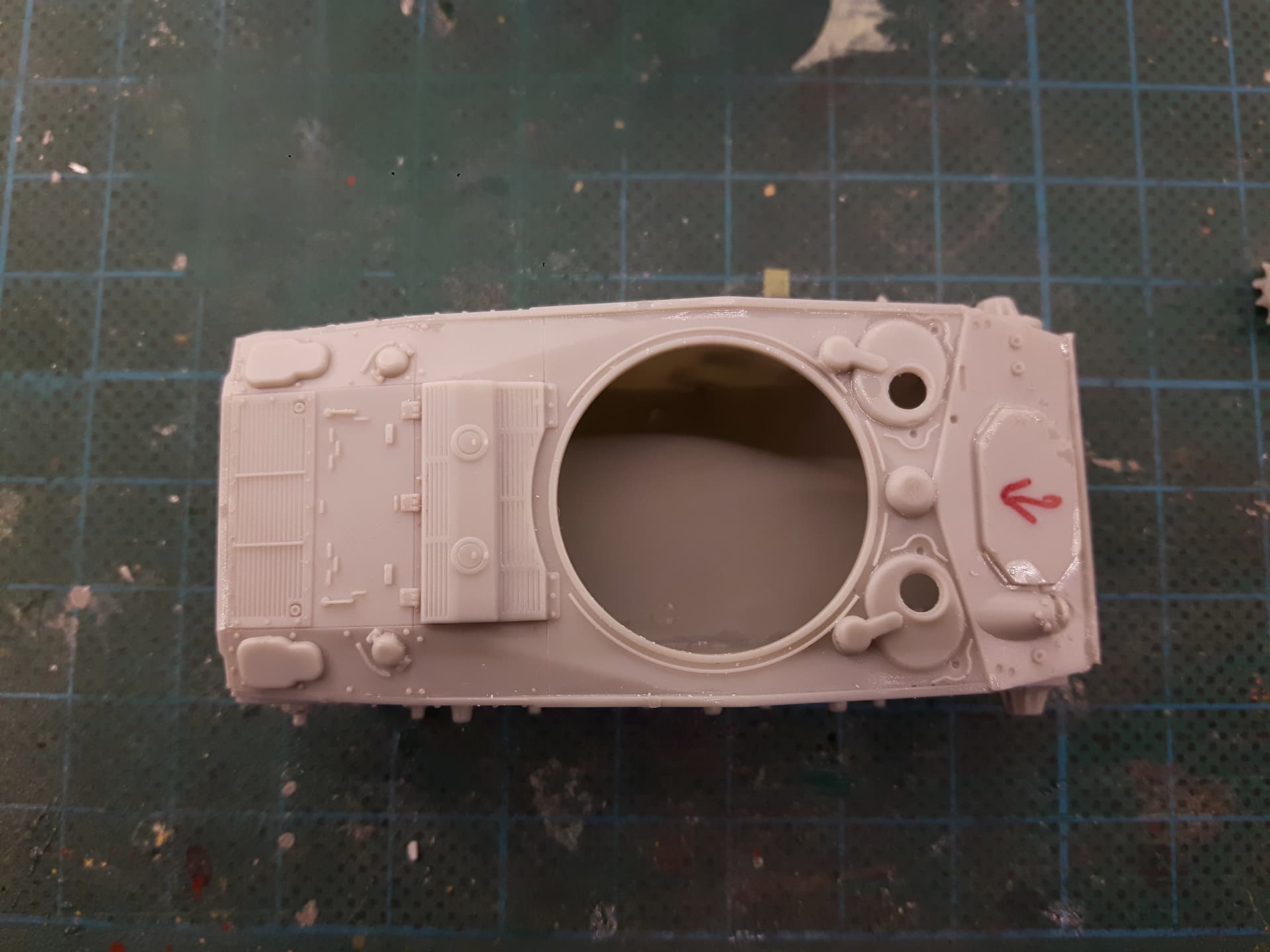
Look closely at the image from the top. Note the hull top part B30 is cut the exact same way as the actual tank, and fits the following way:
- the upper lip of the bottom front armor plate plate sits HIGHER than the upper glacis plate (where the transmission hatch is) – sort of “bulldog bite”.
- the upper glacis lies OVER the sidewalls.
- starting with the driver/radio operator’s hatch plates, and back to the rear wall – the edges of the side armor plates are HIGHER than the hull roof plate.
- the engine deck is FLUSH with the rear wall’s edge.
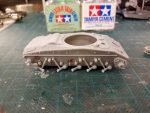
Moving to the suspension the algorithm is to start at either end and glue the suspension arms WITH shock absorbers. This will align the 4 stations correctly, so then you can add the arm at station 3 to align to the rest of them.
There are 2 tiny hooks (part C18) that fit next to station 4 – I am sure many of you will be looking for it in the kit 🙂
Complete operation by adding the track tension mechanism/idler wheel axle. You have a spare for each of them, still be careful to not remove anything but the sprue gates, and to not bend the connecting rods.
Just like on the real thing – there are cutouts in the sprocket stub that are not symmetric:
-
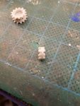
- Sprocket stub
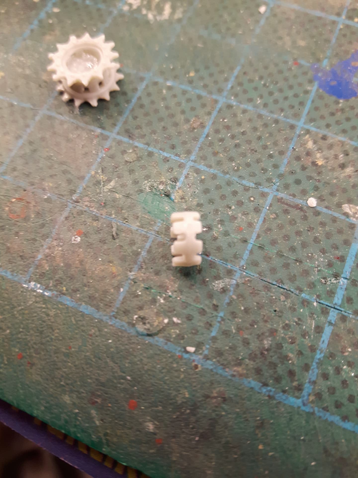
-
- Completed sprockets

To conclude the first part of the build – a few images of the work completed so far.
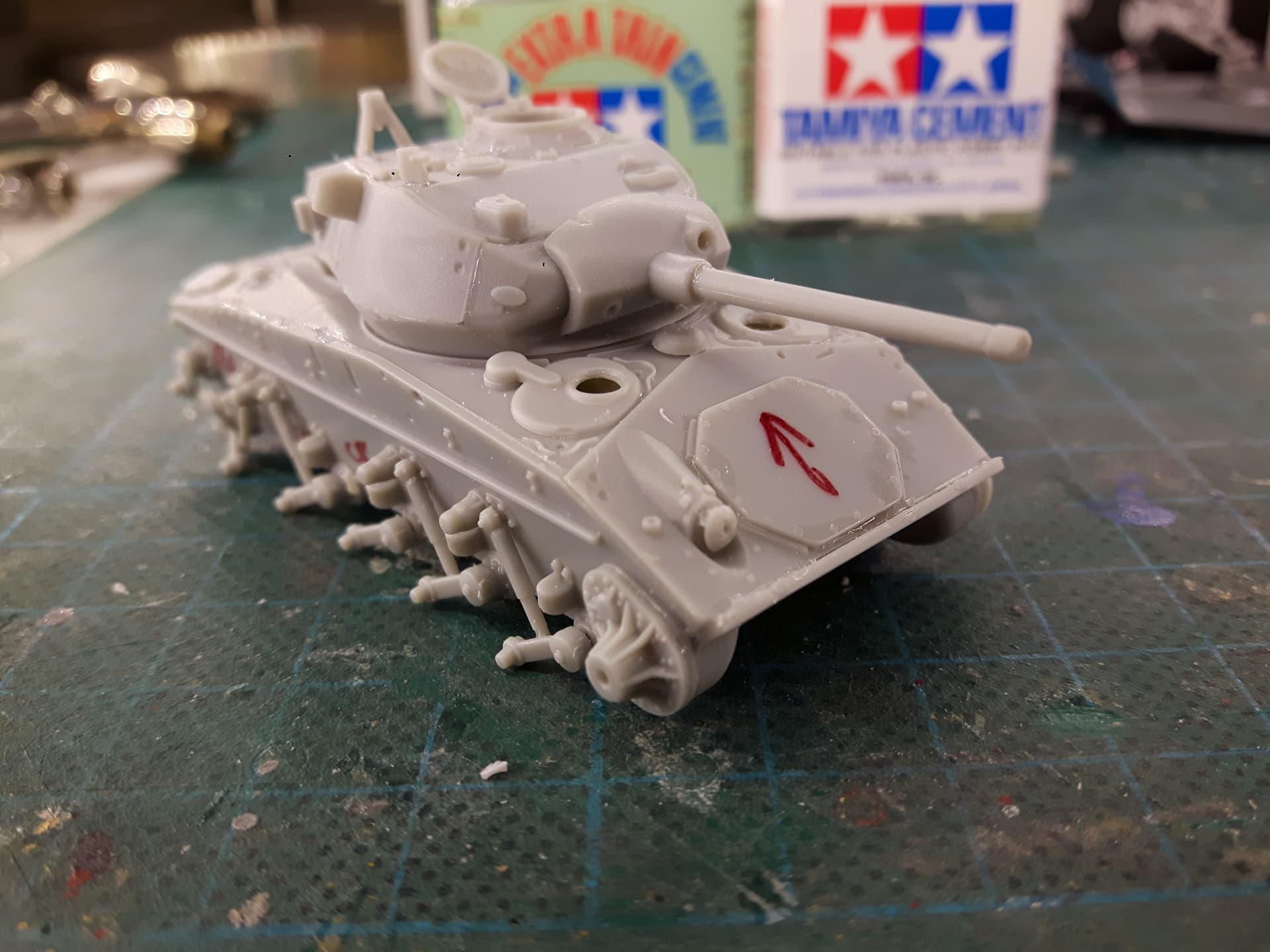
-

- OKB Grigorov M24 Chaffee
-
- Suspension comes into view

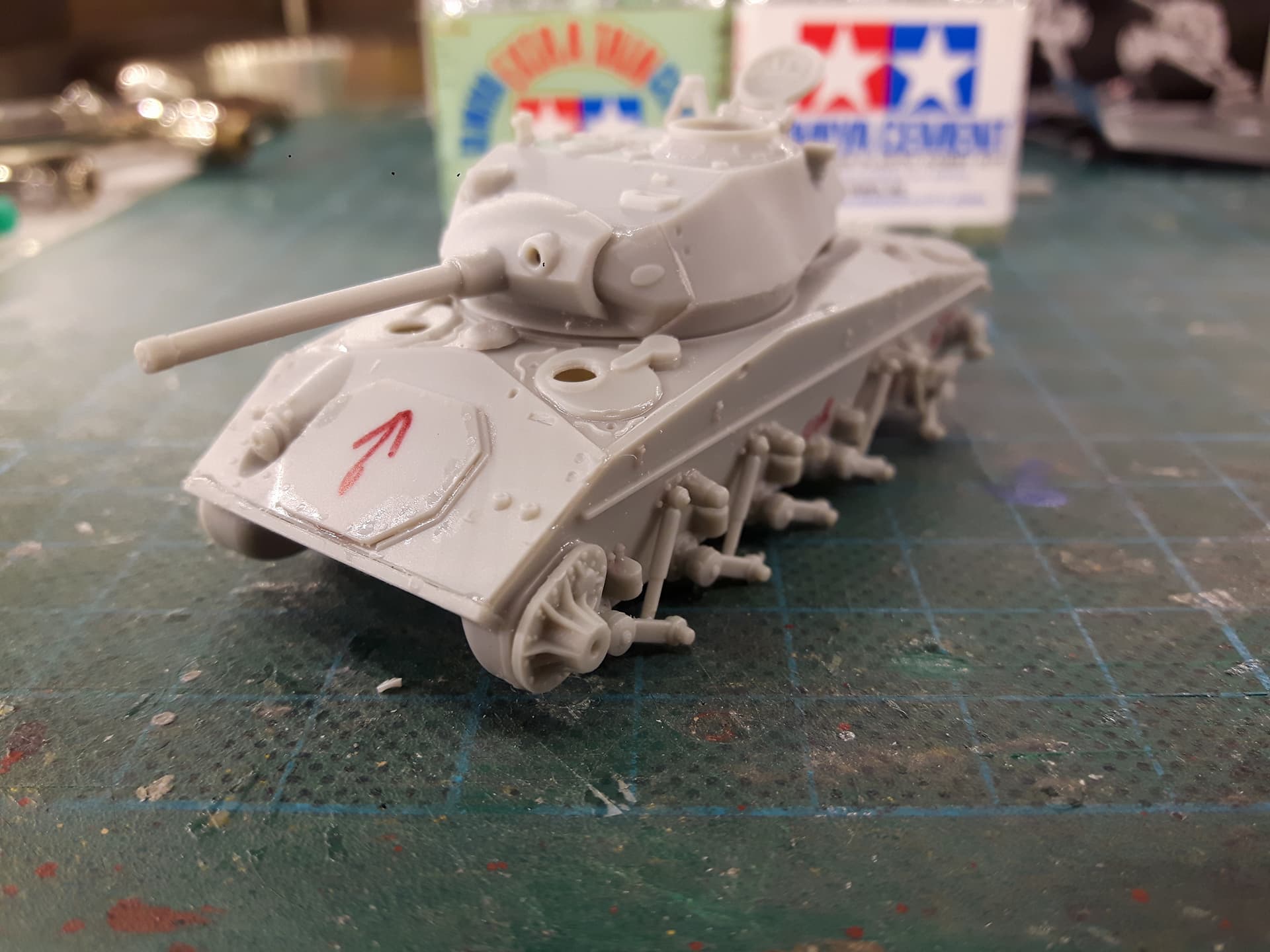
-

- Rear view
-
- Note guard plate, pistol port, antenna base and tripod

Plenty more details to add – see you guys soon!