Last time I reached the point where suspension arms were set in place but no wheels were added. First let me take you back a little and show you the bottom of the hull with some suspension detail.
-
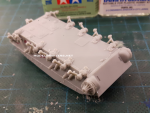
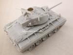
- Front view

-
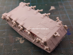
- Rear

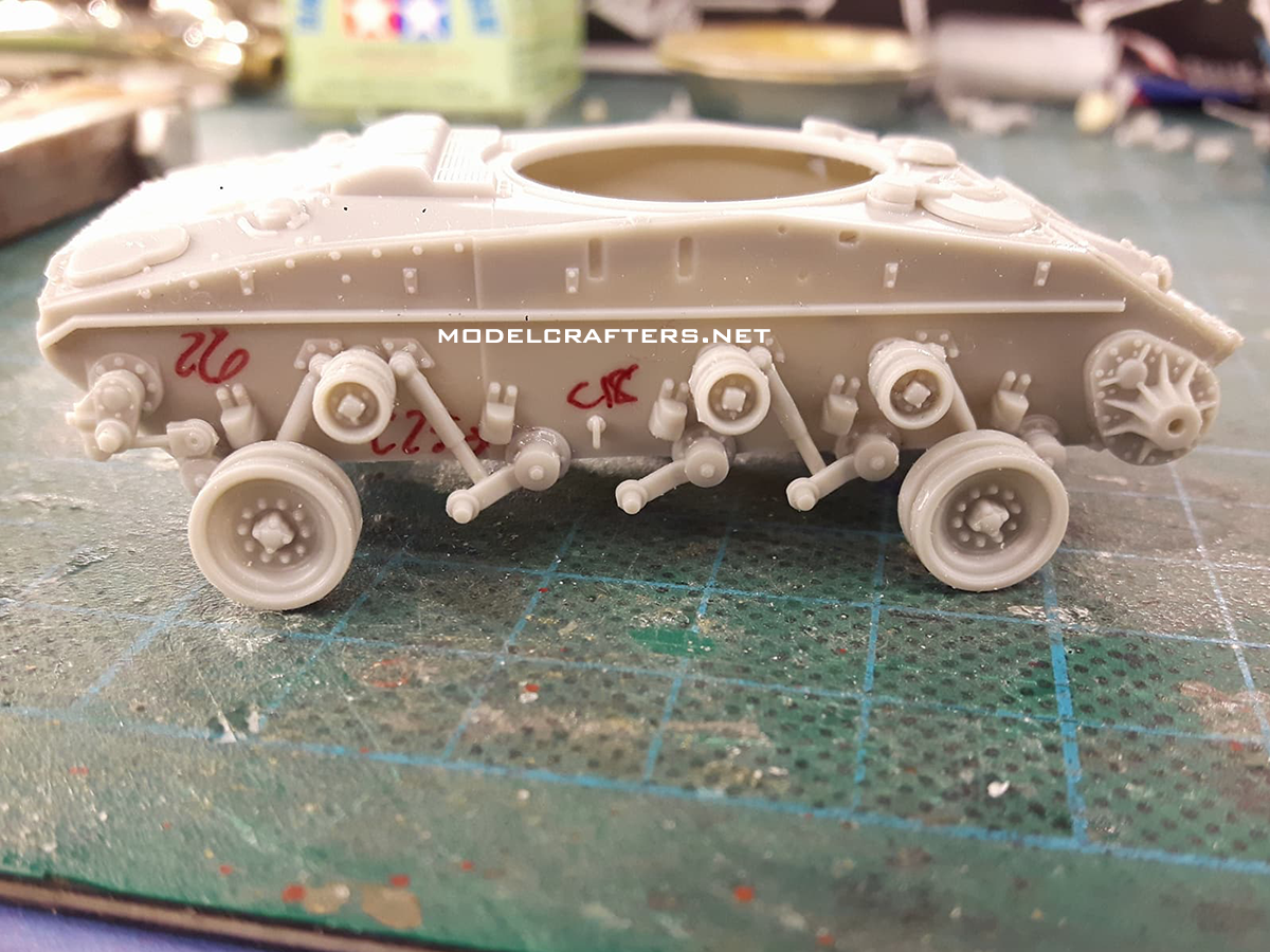
As you can see we have a pretty busy suspension set and this is positively something you want to take your time on. Consult your references on the position of the arms, as I had mine too folded in which caused negative consequences with track runs as you will see shortly.
The main point is this is a very detailed kit, and the only ejection pin mark you’ve seen so far is on the inside of the commander’s hatch. There are no more, period.
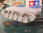
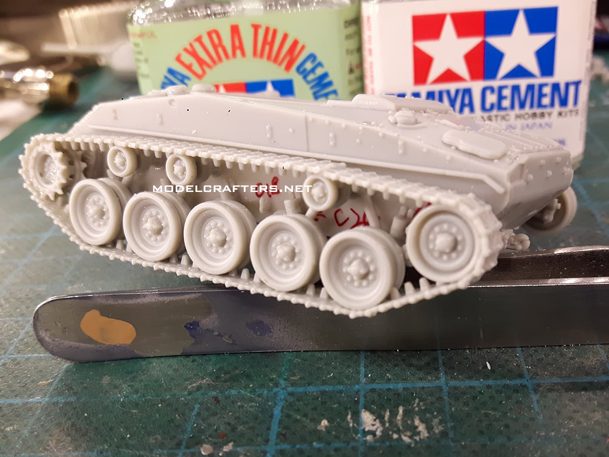
Getting back to the build I moved on to the wheels. I started with the return rollers, gluing their inner halves to the conical posts on the sides. They were a little tight. I then glued the outer halves and squeezed the hull between the 2 bottles of Tamiya glues to align the wheels properly while cleaning the roadwheel halves.
-
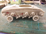
- Return rollers and first roadwheels added
-
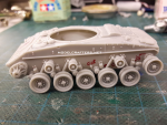
- All roadwheels in place

I first added just 4 roadwheels – one at each end of the hull – to verify (yet again) that I got the hull alignment correct. The remaining wheels were then added and I moved onto the track.
Make sure the middle line of all your wheels is aligned on each side, or you will obtain bent track as I did. On my build the return rollers are further out than the est of the wheels, which made for less that stellar fit – that’s what you get when you don’t pay attention.
Referring directly to mr. Grigorov himself I marked part position on one of his renders to help me in the track assembly process. I glued the longest parts first, then the shorter groups, and finally the single tracks.
-
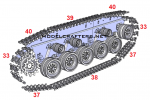
- Track diagram

-

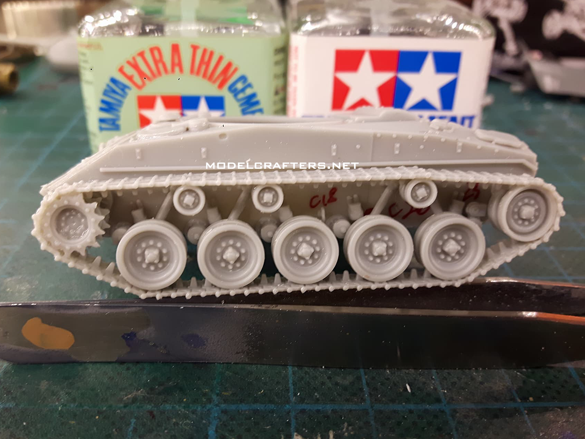
- Left track run
-
- Left track run
Once you clean up the sprue gates correctly track segments and links will fit as they should and you can obtain seamless track run. The plastic is just hard enough to allow you to file the edges without bending or breaking them, it doesn’t chip or leak around your file.
If you cleaned up the sprocket teeth properly you will allow them to enter the links at exactly the openings. I made it on the left site, but teeth seemed too thick on the right one so I had to unglue and modify on a few tracks. I still have 16 individual track links left over after both runs were completed.
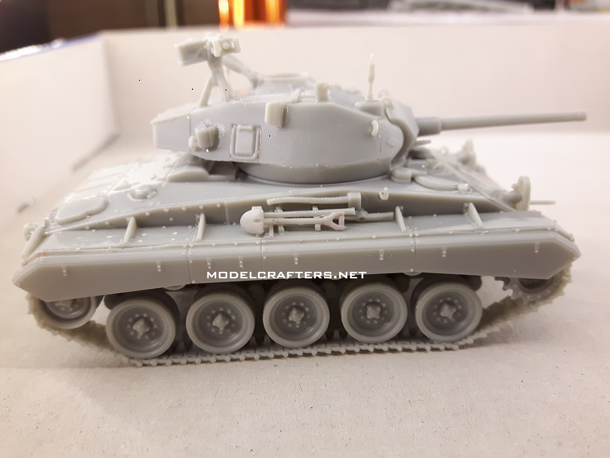
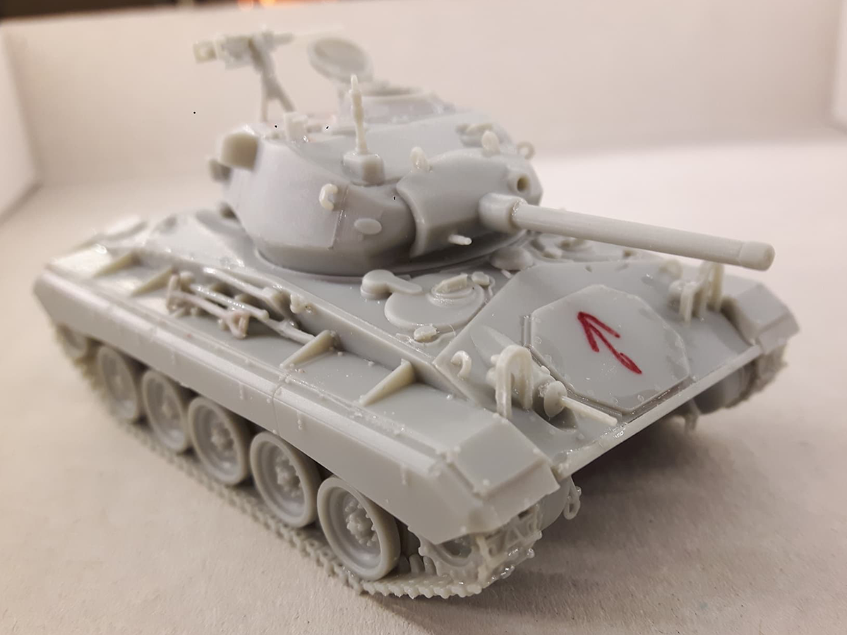
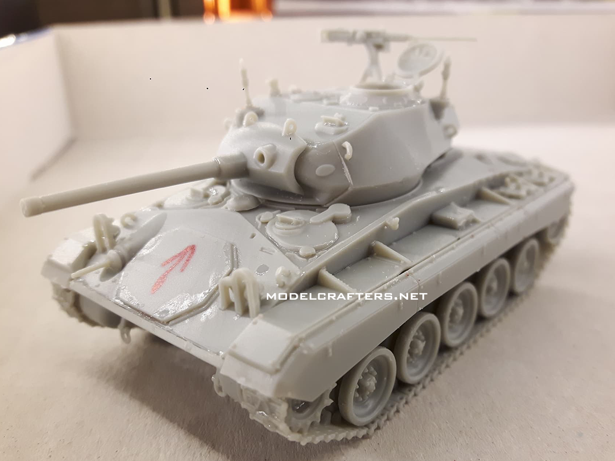
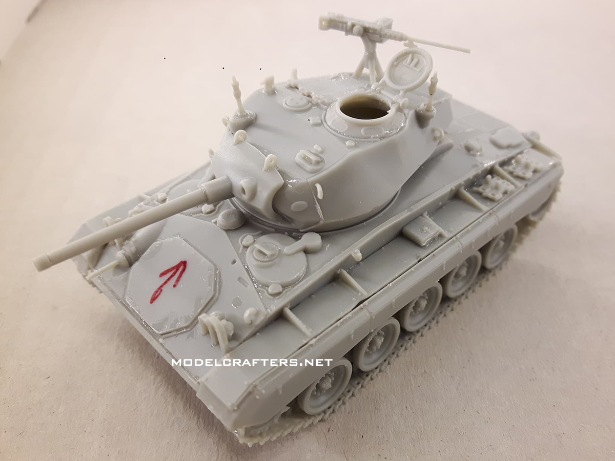
There are a heap of parts I added using the renders as a reference. The lifting hooks (all 10 of them) were the easiest, the 4 periscopes are very hard to NOT lose (I lost 1 trying to add it to the ocmmander’s cupola). Note the separate tools that also have a 2-piece rack they are set on. The rear fender supports are done like inserts that are self-aligning – very useful! The .30 caliber machine guns have a small “droplet” at the tip which I removed and shortened the barrel of the mantlet MG. The .50 cal looks very good for a plastic piece, so do the antenna bases and the rear lights.
In my example (test shot, remember?) the left rear of the fenders is not completely molded, and there are some other areas where the edges are not exactly straight. However all parts are really easy to align, and they’ve sat on there without glue for a while. Even the driver/radioman hatch stops are represented as separate parts which have their slots on the side wall.
The only part I made change to was the right fender. It had attachment points just like the left one, so I cut those out.
-

- OVM tools in place
-
- .30 machine gun
-
- Light guards, periscopes, hatch locks
-
- M24

-
- Ma Deuce, rear lights, fenders

-
- Rear quarter

-

- M24
My impressions:
- very well detailed kit with smart part breakdown,
- intuitive assembly, useful molded-in guides for part alignment,
- great fit,
- no ejection pin marks (well… one),
- optional/posable parts (hatches, periscopes).
Overall great kit, pending for it to hit the market after few minor updates.